2010 INFINITI QX56 power steering
[x] Cancel search: power steeringPage 2213 of 4210
FSU-14
< REMOVAL AND INSTALLATION >
COIL SPRING AND SHOCK ABSORBER
REMOVAL AND INSTALLATION
COIL SPRING AND SHOCK ABSORBER
Removal and InstallationINFOID:0000000005148113
REMOVAL
1. Remove the wheel and tire using power tool.
2. Remove the shock absorber lower bolt using power tool.
3. Remove the three shock absorber upper nuts using power tool.
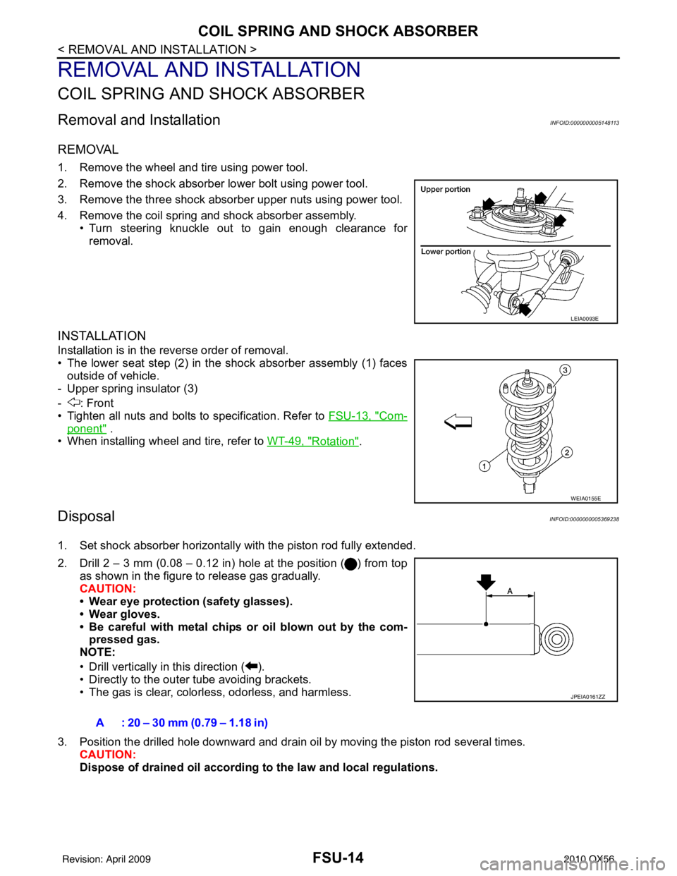
4. Remove the coil spring and shock absorber assembly.• Turn steering knuckle out to gain enough clearance forremoval.
INSTALLATION
Installation is in the reverse order of removal.
• The lower seat step (2) in the shock absorber assembly (1) faces
outside of vehicle.
- Upper spring insulator (3)
- : Front
• Tighten all nuts and bolts to specification. Refer to FSU-13, "
Com-
ponent" .
• When installing wheel and tire, refer to WT-49, "
Rotation".
DisposalINFOID:0000000005369238
1. Set shock absorber horizontally with the piston rod fully extended.
2. Drill 2 – 3 mm (0.08 – 0.12 in) hole at the position ( ) from top
as shown in the figure to release gas gradually.
CAUTION:
• Wear eye protection (safety glasses).
• Wear gloves.
• Be careful with metal chips or oil blown out by the com-pressed gas.
NOTE:
• Drill vertically in this direction ( ).
• Directly to the outer tube avoiding brackets.
• The gas is clear, colorless, odorless, and harmless.
3. Position the drilled hole downward and drain oil by moving the piston rod several times. CAUTION:
Dispose of drained oil according to the law and local regulations.
LEIA0093E
WEIA0155E
A : 20 – 30 mm (0.79 – 1.18 in)
JPEIA0161ZZ
Revision: April 20092010 QX56
Page 2215 of 4210

FSU-16
< REMOVAL AND INSTALLATION >
UPPER LINK
UPPER LINK
Removal and InstallationINFOID:0000000005148115
REMOVAL
1. Remove the wheel and tire using power tool.
2. Remove the fender protector to access upper link. Refer to EXT-23, "
Removal and Installation" .
3. Remove cotter pin and nut from upper link ball joint and discard the cotter pin.
4. Separate upper link ball joint stud from steering knuckle using Tool.
• Support lower link with jack.
5. Remove upper link bolts and nuts, then remove upper link.
INSPECTION AFTER REMOVAL
Upper Link
Check for deformation and cracks. Replace if necessary.
Upper Link Ball Joint
Check for distortion and damage. Replace if necessary.
INSTALLATION
Installation is in the reverse order of removal.
• Tighten all nuts and bolts to specification. Refer to FSU-13, "
Component".
CAUTION:
Use a new cotter pin for installation of upper link ball joint nut.
• When installing wheel and tire, refer to WT-49, "
Rotation".
• After installation, check that the front wheel alignment is within specification. Refer to FSU-6, "
Front Wheel
Alignment" .
Tool number : ST29020001 (J-24319-01)
LEIA0095E
LEIA0096E
Revision: April 20092010 QX56
Page 2216 of 4210
LOWER LINKFSU-17
< REMOVAL AND INSTALLATION >
C
DF
G H
I
J
K L
M A
B
FSU
N
O P
LOWER LINK
Removal and InstallationINFOID:0000000005148116
REMOVAL
1. Remove the wheel and tire using power tool.
2. Remove lower shock absorber bolt.
3. Remove stabilizer bar connecting rod lower nut using power tool, then separate connecting rod from lower
link. Refer to FSU-15, "
Removal and Installation" .
4. Remove drive shaft nut, if equipped. Refer to FA X - 9 , "
Removal and Installation" .
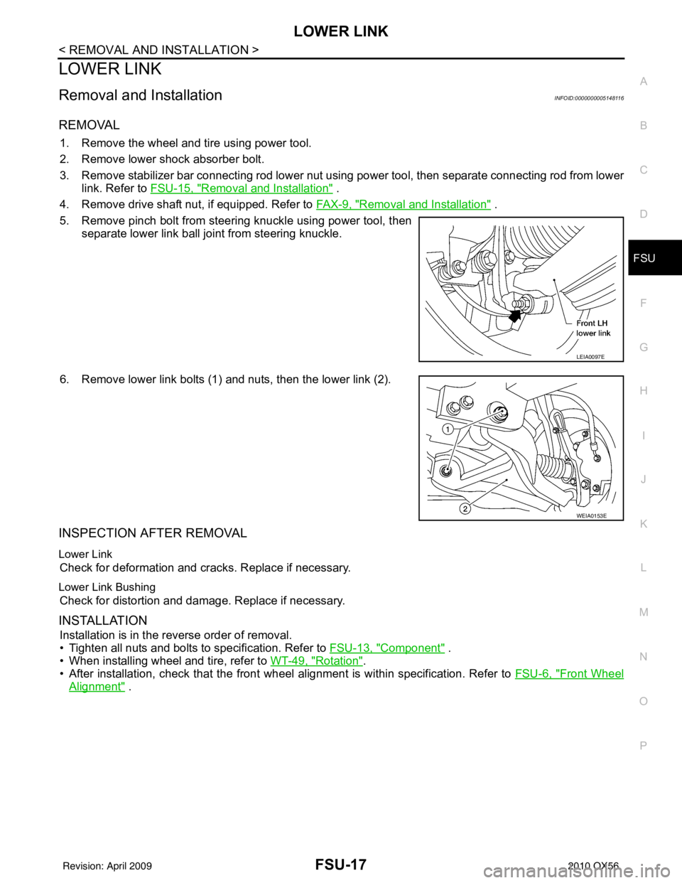
5. Remove pinch bolt from steering knuckle using power tool, then separate lower link ball joint from steering knuckle.
6. Remove lower link bolts (1) and nuts, then the lower link (2).
INSPECTION AFTER REMOVAL
Lower Link
Check for deformation and cracks. Replace if necessary.
Lower Link Bushing
Check for distortion and damage. Replace if necessary.
INSTALLATION
Installation is in the reverse order of removal.
• Tighten all nuts and bolts to specification. Refer to FSU-13, "
Component" .
• When installing wheel and tire, refer to WT-49, "
Rotation".
• After installation, check that the front wheel alignment is within specification. Refer to FSU-6, "
Front Wheel
Alignment" .
LEIA0097E
WEIA0153E
Revision: April 20092010 QX56
Page 2218 of 4210
KNUCKLEFSU-19
< REMOVAL AND INSTALLATION >
C
DF
G H
I
J
K L
M A
B
FSU
N
O P
KNUCKLE
Removal and InstallationINFOID:0000000005148118
REMOVAL
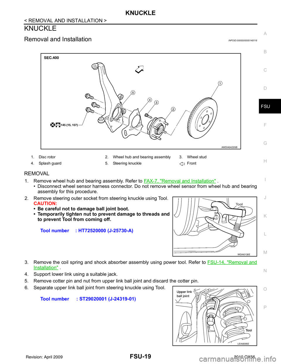
1. Remove wheel hub and bearing assembly. Refer to FAX-7, "Removal and Installation" .
• Disconnect wheel sensor harness connector. Do not remove wheel sensor from wheel hub and bearing
assembly for this procedure.
2. Remove steering outer socket from steering knuckle using Tool. CAUTION:
• Be careful not to damage ball joint boot.
• Temporarily tighten nut to prevent damage to threads andto prevent Tool from coming off.
3. Remove the coil spring and shock absorber assembly using power tool. Refer to FSU-14, "
Removal and
Installation" .
4. Support lower link using a suitable jack.
5. Remove cotter pin and nut from upper link ball joint and discard the cotter pin.
6. Separate upper link ball joint from steering knuckle using Tool.
1. Disc rotor 2. Wheel hub and bearing assembly 3. Wheel stud
4. Splash guard 5. Steering knuckle Front
AWDIA0423GB
Tool number : HT72520000 (J-25730-A)
WGIA0130E
Tool number : ST29020001 (J-24319-01)
LEIA0095E
Revision: April 20092010 QX56
Page 2219 of 4210
FSU-20
< REMOVAL AND INSTALLATION >
KNUCKLE
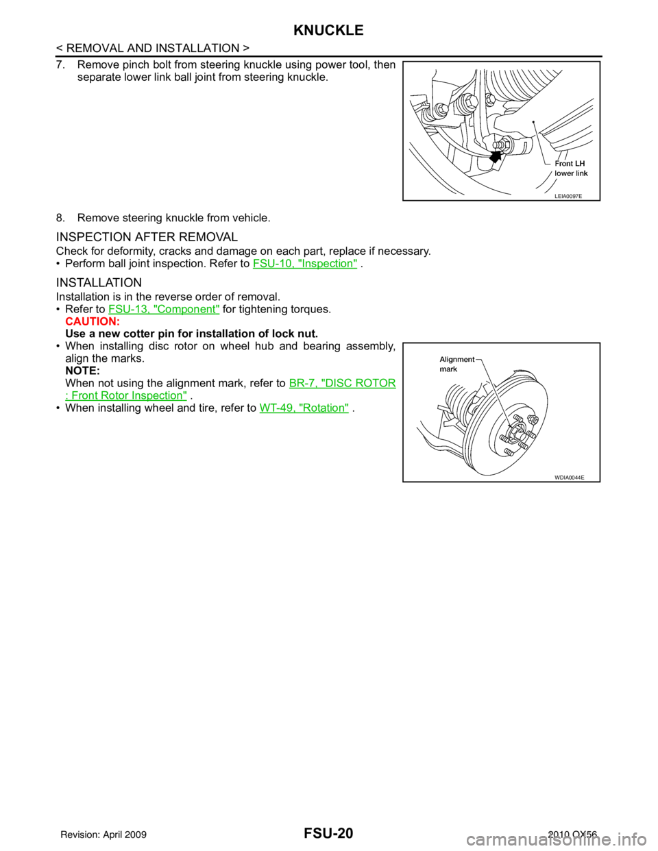
7. Remove pinch bolt from steering knuckle using power tool, thenseparate lower link ball joint from steering knuckle.
8. Remove steering knuckle from vehicle.
INSPECTION AFTER REMOVAL
Check for deformity, cracks and damage on each part, replace if necessary.
• Perform ball joint inspection. Refer to FSU-10, "
Inspection" .
INSTALLATION
Installation is in the reverse order of removal.
• Refer to FSU-13, "
Component" for tightening torques.
CAUTION:
Use a new cotter pin for installation of lock nut.
• When installing disc rotor on wheel hub and bearing assembly, align the marks.
NOTE:
When not using the alignment mark, refer to BR-7, "
DISC ROTOR
: Front Rotor Inspection" .
• When installing wheel and tire, refer to WT-49, "
Rotation" .
LEIA0097E
WDIA0044E
Revision: April 20092010 QX56
Page 2236 of 4210

ABBREVIATIONSGI-13
< HOW TO USE THIS MANUAL >
C
DE
F
G H
I
J
K L
M B
GI
N
O PABBREVIATIONS
Abbreviation ListINFOID:0000000005149579
The following ABBREVIATIONS are used:
ABBREVIATION DESCRIPTION
A/C Air Conditioner
A/T Automatic Transaxle/Transmission
ATF Automatic Transmission Fluid
D
1Drive range 1st gear
D
2Drive range 2nd gear
D
3Drive range 3rd gear
D
4Drive range 4th gear
D5 Drive range 5th gear
FR, RR Front, Rear LH, RH Left-Hand, Right-Hand M/T Manual Transaxle/Transmission
OD Overdrive
P/S Power Steering
SAE Society of Automotive Engineers, Inc.
SDS Service Data and Specifications
SST Special Service Tools
2WD 2-Wheel Drive
4WD 4-Wheel Drive
2
22nd range 2nd gear
2
12nd range 1st gear
1
21st range 2nd gear
1
11st range 1st gear
Revision: April 20092010 QX56
Page 2247 of 4210

GI-24
< PRECAUTION >
PRECAUTIONS
PRECAUTION
PRECAUTIONS
DescriptionINFOID:0000000005149588
Observe the following precautions to ensure safe and proper servicing. These precautions are not
described in each individual section.
Precaution for Supplemental Restraint Syst em (SRS) "AIR BAG" and "SEAT BELT
PRE-TENSIONER"
INFOID:0000000005402047
The Supplemental Restraint System such as “A IR BAG” and “SEAT BELT PRE-TENSIONER”, used along
with a front seat belt, helps to reduce the risk or severity of injury to the driver and front passenger for certain
types of collision. This system includes seat belt switch inputs and dual stage front air bag modules. The SRS
system uses the seat belt switches to determine the front air bag deployment, and may only deploy one front
air bag, depending on the severity of a collision and w hether the front occupants are belted or unbelted.
Information necessary to service the system safely is included in the SR and SB section of this Service Man-
ual.
WARNING:
• To avoid rendering the SRS inopera tive, which could increase the risk of personal injury or death in
the event of a collision which would result in air bag inflation, all maintenance must be performed by
an authorized NISSAN/INFINITI dealer.
• Improper maintenance, including in correct removal and installation of the SRS, can lead to personal
injury caused by unintent ional activation of the system. For re moval of Spiral Cable and Air Bag
Module, see the SR section.
• Do not use electrical test equipmen t on any circuit related to the SRS unless instructed to in this
Service Manual. SRS wiring harn esses can be identified by yellow and/or orange harnesses or har-
ness connectors.
PRECAUTIONS WHEN USING POWER TOOLS (AIR OR ELECTRIC) AND HAMMERS
WARNING:
• When working near the Airbag Diagnosis Sensor Unit or other Airbag System sensors with the Igni-
tion ON or engine running, DO NOT use air or electri c power tools or strike near the sensor(s) with a
hammer. Heavy vibration could activate the sensor( s) and deploy the air bag(s), possibly causing
serious injury.
• When using air or electric power tools or hammers , always switch the Ignition OFF, disconnect the
battery, and wait at least 3 minu tes before performing any service.
Precaution Necessary for Steering W heel Rotation After Battery Disconnect
INFOID:0000000005259102
NOTE:
• This Procedure is applied only to models with Intelligent Key system and NATS (NISSAN ANTI-THEFT SYS-
TEM).
• Remove and install all control units after disconnecting both battery cables with the ignition knob in the
″LOCK ″ position.
• Always use CONSULT-III to perform self-diagnosis as a part of each function inspection after finishing work.
If DTC is detected, perform trouble diagnosis according to self-diagnostic results.
For models equipped with the Intelligent Key system and NATS, an electrically controlled steering lock mech-
anism is adopted on the key cylinder.
For this reason, if the battery is disconnected or if the battery is discharged, the steering wheel will lock and
steering wheel rotation will become impossible.
If steering wheel rotation is required when battery pow er is interrupted, follow the procedure below before
starting the repair operation.
OPERATION PROCEDURE
1. Connect both battery cables. NOTE:
Supply power using jumper cables if battery is discharged.
Revision: April 20092010 QX56
Page 2255 of 4210
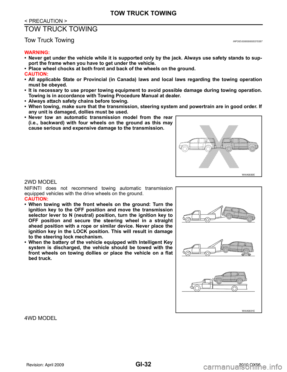
GI-32
< PRECAUTION >
TOW TRUCK TOWING
TOW TRUCK TOWING
Tow Truck TowingINFOID:0000000005370267
WARNING:
• Never get under the vehicle while it is supported only by the jack. Always use safety stands to sup-
port the frame when you have to get under the vehicle.
• Place wheel chocks at both front an d back of the wheels on the ground.
CAUTION:
• All applicable State or Provincial (in Canada) laws and local laws regarding the towing operation
must be obeyed.
• It is necessary to use proper towing equipment to avoid possible damage during towing operation.
Towing is in accordance with Towing Procedure Manual at dealer.
• Always attach safety chains before towing.
• When towing, make sure that the transmission, steering system and powertrain are in good order. If any unit is damaged, dollies must be used.
• Never tow an automatic transmission model from the rear (i.e., backward) with four wh eels on the ground as this may
cause serious and expensive dama ge to the transmission.
2WD MODEL
NIFINTI does not recommend towing automatic transmission
equipped vehicles with the drive wheels on the ground.
CAUTION:
• When towing with the front wheels on the ground: Turn the
ignition key to the OFF posit ion and move the transmission
selector lever to N (neutral) pos ition, turn the ignition key to
OFF position and secure the steering wheel in a straight
ahead position with a rope or similar device. Never place the
ignition key in the LOCK position. This will result in damage
to the steering lock mechanism.
• When the battery of the vehicle equipped with Intelligent Key system is discharged, the vehicle should be towed with the
front wheels on towing dollies or place the vehicle on a flat
bed truck.
4WD MODEL
WAIA0030E
WAIA0031E
Revision: April 20092010 QX56