Page 3791 of 4210

TM-96
< COMPONENT DIAGNOSIS >
CLOSED THROTTLE POSITION AND WIDE OPEN THROTTLE POSITION CIR-
CUIT
CLOSED THROTTLE POSITION AND WIDE OPEN THROTTLE POSITION
CIRCUIT
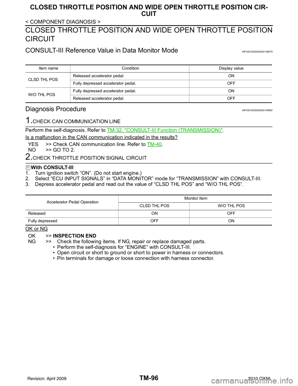
CONSULT-III Reference Value in Data Monitor ModeINFOID:0000000005148679
Diagnosis ProcedureINFOID:0000000005148680
1.CHECK CAN COMMUNICATION LINE
Perform the self-diagnosis. Refer to TM-32, "
CONSULT-III Function (TRANSMISSION)".
Is a malfunction in the CAN communication indicated in the results?
YES >> Check CAN communication line. Refer to TM-40.
NO >> GO TO 2.
2.CHECK THROTTLE POSI TION SIGNAL CIRCUIT
With CONSULT-III
1. Turn ignition switch “ON”. (Do not start engine.)
2. Select “ECU INPUT SIGNALS” in “DATA MONI TOR” mode for “TRANSMISSION” with CONSULT-III.
3. Depress accelerator pedal and read out the value of “CLSD THL POS” and “W/O THL POS”.
OK or NG
OK >> INSPECTION END
NG >> Check the following items. If NG, repair or replace damaged parts. • Perform the self-diagnosis for “ENGINE” with CONSULT-III.
• Open circuit or short to ground or shor t to power in harness or connectors.
• Pin terminals for damage or loos e connection with harness connector.
Item name Condition Display value
CLSD THL POS Released accelerator pedal.
ON
Fully depressed accelerator pedal. OFF
W/O THL POS Fully depressed accelerator pedal.
ON
Released accelerator pedal. OFF
Accelerator Pedal OperationMonitor Item
CLSD THL POS W/O THL POS
Released ONOFF
Fully depressed OFFON
Revision: April 20092010 QX56
Page 3792 of 4210

BRAKE SIGNAL CIRCUITTM-97
< COMPONENT DIAGNOSIS >
CEF
G H
I
J
K L
M A
B
TM
N
O P
BRAKE SIGNAL CIRCUIT
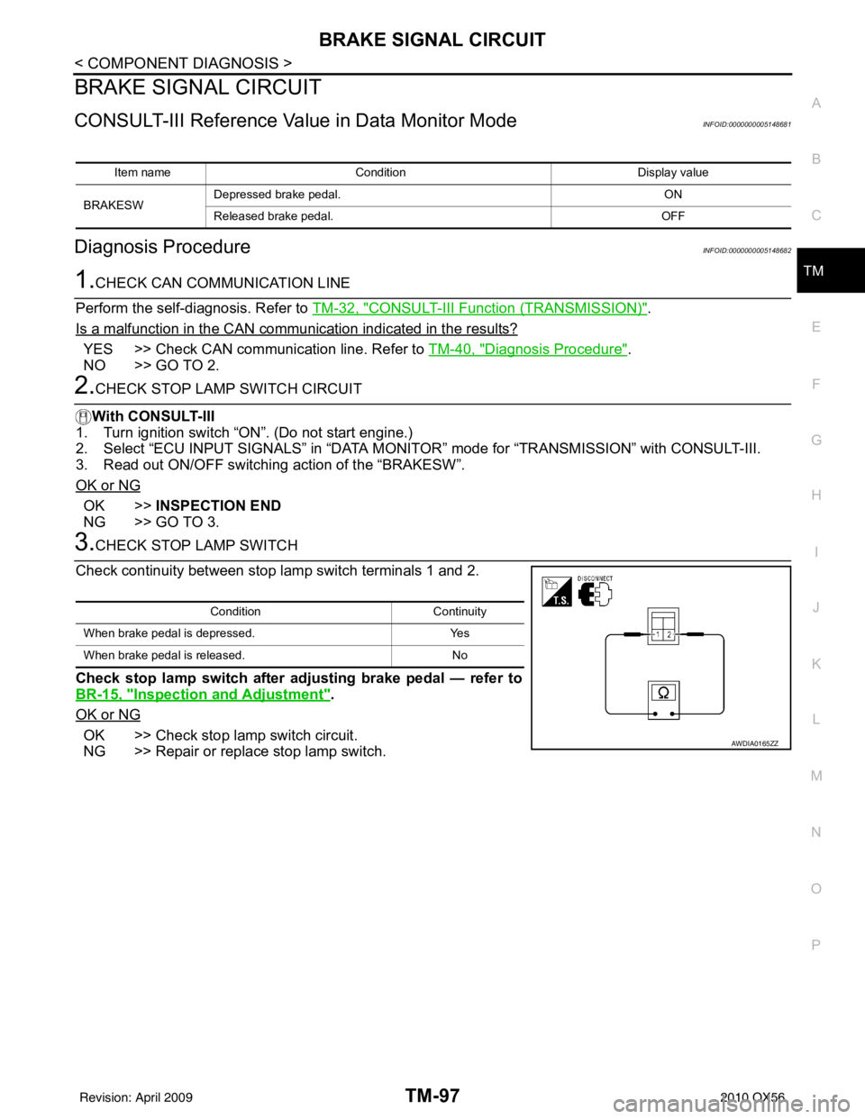
CONSULT-III Reference Val ue in Data Monitor ModeINFOID:0000000005148681
Diagnosis ProcedureINFOID:0000000005148682
1.CHECK CAN COMMUNICATION LINE
Perform the self-diagnosis. Refer to TM-32, "
CONSULT-III Function (TRANSMISSION)".
Is a malfunction in the CAN communication indicated in the results?
YES >> Check CAN communication line. Refer to TM-40, "Diagnosis Procedure".
NO >> GO TO 2.
2.CHECK STOP LAMP SWITCH CIRCUIT
With CONSULT-III
1. Turn ignition switch “ON”. (Do not start engine.)
2. Select “ECU INPUT SIGNALS” in “DATA MONITO R” mode for “TRANSMISSION” with CONSULT-III.
3. Read out ON/OFF switching action of the “BRAKESW”.
OK or NG
OK >> INSPECTION END
NG >> GO TO 3.
3.CHECK STOP LAMP SWITCH
Check continuity between stop lamp switch terminals 1 and 2.
Check stop lamp switch after adjusting brake pedal — refer to
BR-15, "
Inspection and Adjustment".
OK or NG
OK >> Check stop lamp switch circuit.
NG >> Repair or replace stop lamp switch.
Item name Condition Display value
BRAKESW Depressed brake pedal.
ON
Released brake pedal. OFF
ConditionContinuity
When brake pedal is depressed. Yes
When brake pedal is released. No
AWDIA0165ZZ
Revision: April 20092010 QX56
Page 3801 of 4210

TM-106
< ECU DIAGNOSIS >
TCM
ECU DIAGNOSIS
TCM
Reference ValueINFOID:0000000005148688
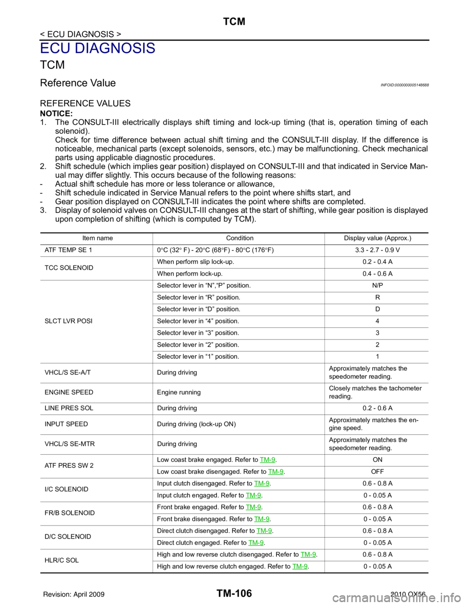
REFERENCE VALUES
NOTICE:
1. The CONSULT-III electrically displays shift timing and lock-up timing (that is, operation timing of eachsolenoid).
Check for time difference between actual shift timi ng and the CONSULT-III display. If the difference is
noticeable, mechanical parts (except solenoids, sens ors, etc.) may be malfunctioning. Check mechanical
parts using applicable diagnostic procedures.
2. Shift schedule (which implies gear position) display ed on CONSULT-III and that indicated in Service Man-
ual may differ slightly. This occurs because of the following reasons:
- Actual shift schedule has more or less tolerance or allowance,
- Shift schedule indicated in Service Manual refers to the point where shifts start, and
- Gear position displayed on CONSULT-III indicates the point where shifts are completed.
3. Display of solenoid valves on CONSULT-III changes at t he start of shifting, while gear position is displayed
upon completion of shifting (which is computed by TCM).
Item name Condition Display value (Approx.)
AT F T E M P S E 1 0°C (32 ° F) - 20 °C (68 °F) - 80 °C (176 °F) 3.3 - 2.7 - 0.9 V
TCC SOLENOID When perform slip lock-up.
0.2 - 0.4 A
When perform lock-up. 0.4 - 0.6 A
SLCT LVR POSI Selector lever in “N”,“P” position.
N/P
Selector lever in “R” position. R
Selector lever in “D” position. D
Selector lever in “4” position. 4
Selector lever in “3” position. 3
Selector lever in “2” position. 2
Selector lever in “1” position. 1
VHCL/S SE-A/T During driving Approximately matches the
speedometer reading.
ENGINE SPEED Engine running Closely matches the tachometer
reading.
LINE PRES SOL During driving 0.2 - 0.6 A
INPUT SPEED During driving (lock-up ON) Approximately matches the en-
gine speed.
VHCL/S SE-MTR During driving Approximately matches the
speedometer reading.
ATF PRES SW 2 Low coast brake engaged. Refer to
TM-9
.ON
Low coast brake disengaged. Refer to TM-9
.OFF
I/C SOLENOID Input clutch disengaged. Refer to
TM-9
.0.6 - 0 .8 A
Input clutch engaged. Refer to TM-9
.0 - 0 .0 5 A
FR/B SOLENOID Front brake engaged. Refer to
TM-9
.0 .6 - 0 .8 A
Front brake disengaged. Refer to TM-9
.0 - 0 .0 5 A
D/C SOLENOID Direct clutch disengaged. Refer to
TM-9
.0.6 - 0 .8 A
Direct clutch engaged. Refer to TM-9
.0 - 0 .0 5 A
HLR/C SOL High and low reverse clutch disengaged. Refer to
TM-9
.0.6 - 0 .8 A
High and low reverse clutch engaged. Refer to TM-9
.0 - 0 .0 5 A
Revision: April 20092010 QX56
Page 3802 of 4210

TCM
TM-107
< ECU DIAGNOSIS >
C EF
G H
I
J
K L
M A
B
TM
N
O P
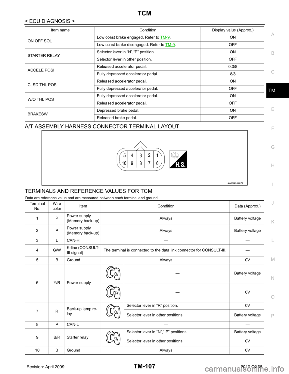
A/T ASSEMBLY HARNESS CONNECTOR TERMINAL LAYOUT
TERMINALS AND REFERENCE VALUES FOR TCM
Data are reference value and are measured between each terminal and ground.
ON OFF SOL Low coast brake engaged. Refer to
TM-9.ON
Low coast brake disengaged. Refer to TM-9
.OFF
STARTER RELAY Selector lever in
“N”,“P” position. ON
Selector lever in other position. OFF
ACCELE POSI Released accelerator pedal.
0.0/8
Fully depressed accelerator pedal. 8/8
CLSD THL POS Released accelerator pedal.
ON
Fully depressed accelerator pedal. OFF
W/O THL POS Fully depressed accelerator pedal.
ON
Released accelerator pedal. OFF
BRAKESW Depressed brake pedal.
ON
Released brake pedal. OFF
Item name
Condition Display value (Approx.)
AWDIA0348ZZ
Te r m i n a l
No. Wire
color Item
ConditionData (Approx.)
1P Power supply
(Memory back-up)
Always
Battery voltage
2P Power supply
(Memory back-up) Always
Battery voltage
3 L CAN-H ——
4G/W K-line (CONSULT-
III signal) The terminal is connected to the data link connector for CONSULT-III. —
5 B Ground Always0V
6Y/RPower supply —
Battery voltage
—0 V
7R Back-up lamp re-
lay Selector lever in “R” position.
0V
Selector lever in other positions. Battery voltage
8 P CAN-L ——
9 B/R Starter relay Selector lever in “N”,“ P”
positions. Battery voltage
Selector lever in other positions. 0V
10 B Ground Always0V
Revision: April 20092010 QX56
Page 3803 of 4210
TM-108
< ECU DIAGNOSIS >
TCM
Wiring Diagram —A/T CONTROL SYSTEM —
INFOID:0000000005148689
ABDWA0117GB
Revision: April 20092010 QX56
Page 3804 of 4210
TCM
TM-109
< ECU DIAGNOSIS >
C EF
G H
I
J
K L
M A
B
TM
N
O P
AADWA0067GB
Revision: April 20092010 QX56
Page 3805 of 4210
TM-110
< ECU DIAGNOSIS >
TCM
AADIA0122GB
Revision: April 20092010 QX56
Page 3806 of 4210
TCM
TM-111
< ECU DIAGNOSIS >
C EF
G H
I
J
K L
M A
B
TM
N
O P
ABDIA0047GB
Revision: April 20092010 QX56