2010 INFINITI QX56 battery
[x] Cancel search: batteryPage 3838 of 4210
PRECAUTIONSTM-143
< PRECAUTION >
CEF
G H
I
J
K L
M A
B
TM
N
O P
PRECAUTION
PRECAUTIONS
Precaution for Supplemental Restraint System (SRS) "AIR BAG" and "SEAT BELT
PRE-TENSIONER"
INFOID:0000000005148716
The Supplemental Restraint System such as “AIR BAG” and “SEAT BELT PRE-TENSIONER”, used along
with a front seat belt, helps to reduce the risk or severi ty of injury to the driver and front passenger for certain
types of collision. This system includes seat belt switch inputs and dual stage front air bag modules. The SRS
system uses the seat belt switches to determine the front air bag deployment, and may only deploy one front
air bag, depending on the severity of a collision and w hether the front occupants are belted or unbelted.
Information necessary to service the system safely is included in the SR and SB section of this Service Man-
ual.
WARNING:
• To avoid rendering the SRS inoper ative, which could increase the risk of personal injury or death in
the event of a collision which would result in air bag inflation, all maintenance must be performed by
an authorized NISSAN/INFINITI dealer.
• Improper maintenance, including in correct removal and installation of the SRS, can lead to personal
injury caused by unintentional act ivation of the system. For removal of Spiral Cable and Air Bag
Module, see the SR section.
• Do not use electrical test equipm ent on any circuit related to the SRS unless instructed to in this
Service Manual. SRS wiring harnesses can be identi fied by yellow and/or orange harnesses or har-
ness connectors.
Precaution for On Board Diagnosis (OBD) System of A/T and EngineINFOID:0000000005148717
The ECM has an on board diagnostic system . It will light up the malfunction indicator lamp (MIL) to warn the
driver of a malfunction causing emission deterioration.
CAUTION:
• Be sure to turn the ignition switch “OFF” and disconnect the negative battery cable before any repair or inspection work. The open/short circuit of related switches, sen sors, solenoid valves, etc. Will
cause the MIL to light up.
• Be sure to connect and lock the connectors secure ly after work. A loose (unlocked) connector will
cause the MIL to light up due to an open circuit. (Be sure the connector is free from water, grease,
dirt, bent terminals, etc.)
• Be sure to route and secure the harnesses properly after work. Interference of the harness with a
bracket, etc. May cause the MIL to li ght up due to a short circuit.
• Be sure to connect rubber tubes properly afte r work. A misconnected or disconnected rubber tube
may cause the MIL to light up due to a malfunction of the EGR system or fuel injection system, etc.
• Be sure to erase the unnecessary malfunction informa tion (repairs completed) from the TCM and
ECM before returning the vehicle to the customer.
PrecautionINFOID:0000000005148718
NOTE:
If any malfunctions occur in th e RE5R05A model transmission, repl ace the entire transmission assem-
bly.
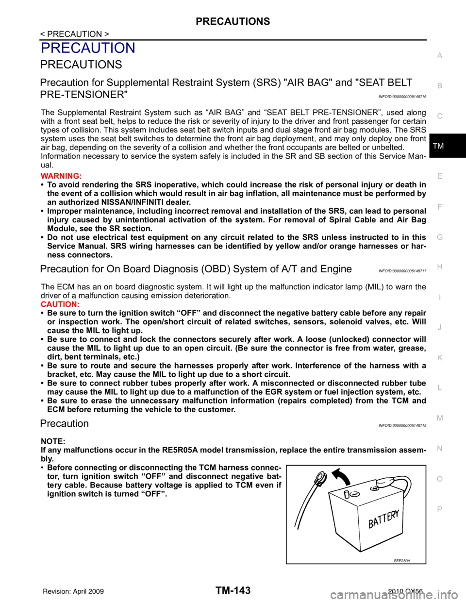
• Before connecting or disconn ecting the TCM harness connec-
tor, turn ignition switch “O FF” and disconnect negative bat-
tery cable. Because battery voltage is applied to TCM even if
ignition switch is turned “OFF”.
SEF289H
Revision: April 20092010 QX56
Page 3867 of 4210
TM-172
< ON-VEHICLE REPAIR >
CONTROL VALVE WITH TCM
CONTROL VALVE WITH TCM
Control Valve with TCM and A/T Fluid Temperature Sensor 2 and PlugINFOID:0000000005148741
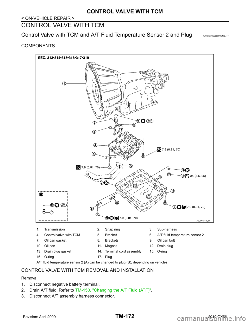
COMPONENTS
CONTROL VALVE WITH TCM REMOVAL AND INSTALLATION
Removal
1. Disconnect negative battery terminal.
2. Drain A/T fluid. Refer to TM-150, "
Changing the A/T Fluid (ATF)".
3. Disconnect A/T assembly harness connector.
1. Transmission 2. Snap ring3. Sub-harness
4. Control valve with TCM 5. Bracket 6. A/T fluid temperature sensor 2
7. Oil pan gasket 8. Brackets9. Oil pan bolt
10. Oil pan 11. Magnet12. Drain plug
13. Drain plug gasket 14. Terminal cord assembly 15. O-ring
16. O-ring 17. Plug
A/T fluid temperature sensor 2 (A) can be changed to plug (B), depending on vehicles.
JSDIA1314GB
Revision: April 20092010 QX56
Page 3875 of 4210
TM-180
< ON-VEHICLE REPAIR >
CONTROL VALVE WITH TCM
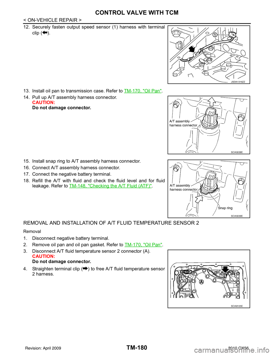
12. Securely fasten output speed sensor (1) harness with terminalclip ( ).
13. Install oil pan to transmission case. Refer to TM-170, "
Oil Pan".
14. Pull up A/T assembly harness connector. CAUTION:
Do not damage connector.
15. Install snap ring to A/T assembly harness connector.
16. Connect A/T assembly harness connector.
17. Connect the negative battery terminal.
18. Refill the A/T with fluid and check the fluid level and for fluid leakage. Refer to TM-148, "
Checking the A/T Fluid (ATF)".
REMOVAL AND INSTALLATION OF A/T FLUID TEMPERATURE SENSOR 2
Removal
1. Disconnect negative battery terminal.
2. Remove oil pan and oil pan gasket. Refer to TM-170, "
Oil Pan".
3. Disconnect A/T fluid temperat ure sensor 2 connector (A).
CAUTION:
Do not damage connector.
4. Straighten terminal clip ( ) to free A/T fluid temperature sensor 2 harness.
JSDIA1316ZZ
SCIA5038E
SCIA5039E
SCIA8125E
Revision: April 20092010 QX56
Page 3877 of 4210
TM-182
< ON-VEHICLE REPAIR >
CONTROL VALVE WITH TCM
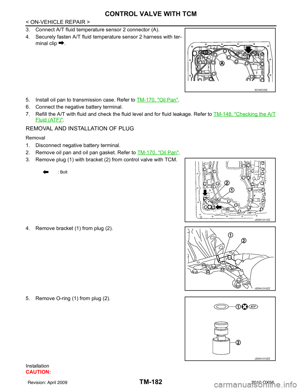
3. Connect A/T fluid temperature sensor 2 connector (A).
4. Securely fasten A/T fluid temperature sensor 2 harness with ter-minal clip .
5. Install oil pan to transmission case. Refer to TM-170, "
Oil Pan".
6. Connect the negative battery terminal.
7. Refill the A/T with fluid and check the fluid level and for fluid leakage. Refer to TM-148, "
Checking the A/T
Fluid (ATF)".
REMOVAL AND INSTALLATION OF PLUG
Removal
1. Disconnect negative battery terminal.
2. Remove oil pan and oil pan gasket. Refer to TM-170, "
Oil Pan".
3. Remove plug (1) with bracket (2) from control valve with TCM.
4. Remove bracket (1) from plug (2).
5. Remove O-ring (1) from plug (2).
Installation
CAUTION:
SCIA8125E
: Bolt
JSDIA1311ZZ
JSDIA1312ZZ
JSDIA1313ZZ
Revision: April 20092010 QX56
Page 3878 of 4210
CONTROL VALVE WITH TCMTM-183
< ON-VEHICLE REPAIR >
CEF
G H
I
J
K L
M A
B
TM
N
O P
After completing installation, check A/T fluid leakage and fluid level. Refer to TM-148, "Checking the A/
T Fluid (ATF)".
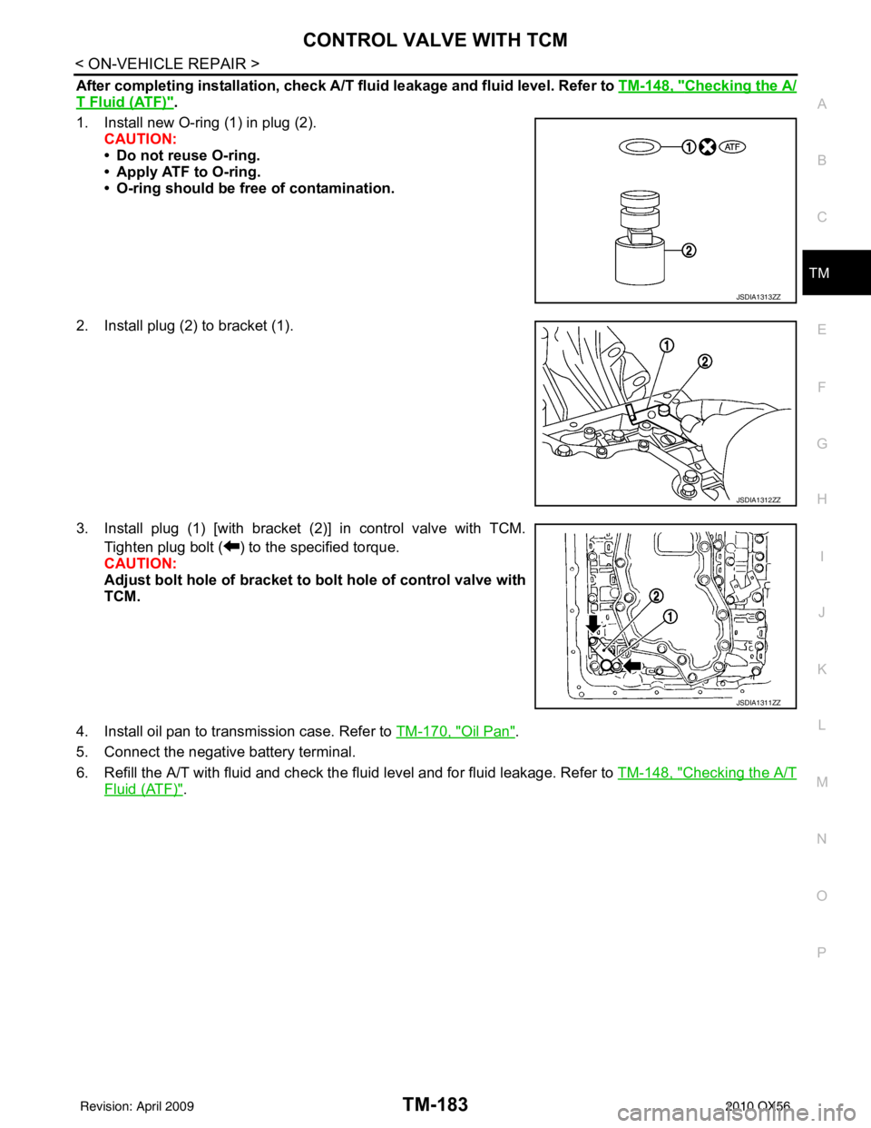
1. Install new O-ring (1) in plug (2). CAUTION:
• Do not reuse O-ring.
• Apply ATF to O-ring.
• O-ring should be free of contamination.
2. Install plug (2) to bracket (1).
3. Install plug (1) [with bracket (2)] in control valve with TCM. Tighten plug bolt ( ) to the specified torque.
CAUTION:
Adjust bolt hole of bracket to bolt hole of control valve with
TCM.
4. Install oil pan to transmission case. Refer to TM-170, "
Oil Pan".
5. Connect the negative battery terminal.
6. Refill the A/T with fluid and check the fluid level and for fluid leakage. Refer to TM-148, "
Checking the A/T
Fluid (ATF)".
JSDIA1313ZZ
JSDIA1312ZZ
JSDIA1311ZZ
Revision: April 20092010 QX56
Page 3881 of 4210
TM-186
< REMOVAL AND INSTALLATION >
TRANSMISSION ASSEMBLY
REMOVAL AND INSTALLATION
TRANSMISSION ASSEMBLY
Removal and Installation (2WD)INFOID:0000000005148743
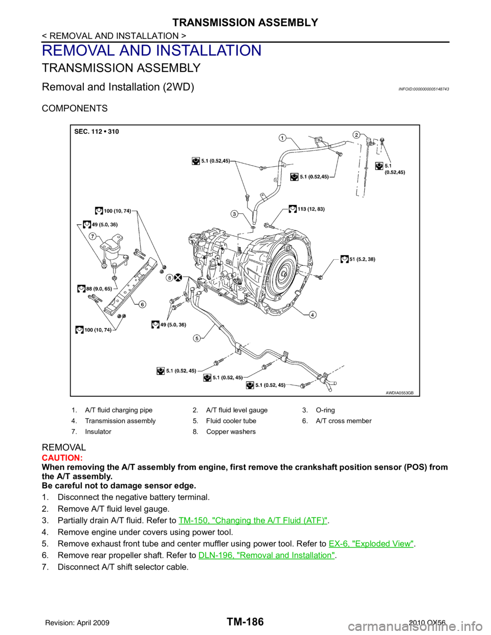
COMPONENTS
REMOVAL
CAUTION:
When removing the A/T assembly from engine, first remove the crankshaft position sensor (POS) from
the A/T assembly.
Be careful not to damage sensor edge.
1. Disconnect the negative battery terminal.
2. Remove A/T fluid level gauge.
3. Partially drain A/T fluid. Refer to TM-150, "
Changing the A/T Fluid (ATF)".
4. Remove engine under covers using power tool.
5. Remove exhaust front tube and center muffler using power tool. Refer to EX-6, "
Exploded View".
6. Remove rear propeller shaft. Refer to DLN-196, "
Removal and Installation".
7. Disconnect A/T shift selector cable.
1. A/T fluid charging pipe 2. A/T fluid level gauge 3. O-ring
4. Transmission assembly 5. Fluid cooler tube6. A/T cross member
7. Insulator 8. Copper washers
AWDIA0553GB
Revision: April 20092010 QX56
Page 3884 of 4210
TRANSMISSION ASSEMBLYTM-189
< REMOVAL AND INSTALLATION >
CEF
G H
I
J
K L
M A
B
TM
N
O P
REMOVAL
CAUTION:
When removing the A/T assembly from engine, firs t remove the crankshaft position sensor (POS) from
the A/T assembly.
Be careful not to damage sensor edge.
1. Disconnect the negative battery terminal.
2. Remove A/T fluid level gauge.
3. Partially drain A/T fluid. Refer to TM-150, "
Changing the A/T Fluid (ATF)".
4. Remove engine under cover and transfer under cover using power tool.
5. Remove exhaust front tube and center muffler using power tool. Refer to EX-6, "
Exploded View".
6. Remove propeller shafts. Refer to DLN-186, "
Removal and Installation" (front) and DLN-196, "Removal
and Installation" (rear).
7. Disconnect A/T shift selector cable.
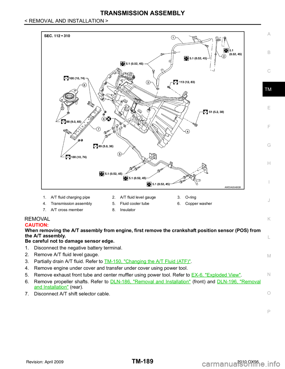
1. A/T fluid charging pipe 2. A/T fluid level gauge3. O-ring
4. Transmission assembly 5. Fluid cooler tube6. Copper washer
7. A/T cross member 8. Insulator
AWDIA0548GB
Revision: April 20092010 QX56
Page 3963 of 4210
VTL-1
VENTILATION, HEATER & AIR CONDITIONER
C
DE
F
G H
J
K L
M
SECTION VTL
A
B
VTL
N
O P
CONTENTS
VENTILATION SYSTEM
PRECAUTION ....... ........................................2
PRECAUTIONS .............................................. .....2
Precaution for Supplemental Restraint System
(SRS) "AIR BAG" and "SEAT BELT PRE-TEN-
SIONER" ............................................................. ......
2
Precaution Necessary for Steering Wheel Rota-
tion After Battery Disconnect ............................... ......
2
Precaution for Working with HFC-134a (R-134a) ......3
Precaution for Procedure without Cowl Top Cover ......3
PREPARATION ............................................4
PREPARATION .............................................. .....4
Commercial Service Tool .................................... ......4
FUNCTION DIAGNOSIS ...............................5
IN-CABIN MICROFILTER .............................. .....5
Description .......................................................... ......5
ON-VEHICLE MAINTENANCE .....................6
IN-CABIN MICROFILTER .............................. .....6
Removal and Installation ...........................................6
ON-VEHICLE REPAIR .... ..............................7
CONTROL UNIT ..................................................7
Removal and Installation ...........................................7
IN-VEHICLE SENSOR ................................... .....9
Removal and Installation ...........................................9
OPTICAL SENSOR ........................................ ....10
Removal and Installation .........................................10
INTAKE SENSOR ..............................................11
Removal and Installation .........................................11
BLOWER MOTOR .......................................... ....12
Component .......................................................... ....12
Removal and Installation .........................................12
VARIABLE BLOWER CONTROL .....................14
Components ............................................................14
Removal and Installation .........................................15
HEATER & COOLING UNIT ASSEMBLY ........16
Component ..............................................................16
Removal and Installation .........................................17
EVAPORATOR .................................................19
Removal and Installation for Front Evaporator ........19
Removal and Installation for Rear Evaporator .........20
EXPANSION VALVE .........................................22
Removal and Installation for Rear Expansion
Valve .................................................................... ....
22
HEATER CORE .................................................23
Component ..............................................................23
Removal and Installation .........................................24
DEFROSTER DOOR MOTOR ..........................26
Removal and Installation .........................................26
INTAKE DOOR MOTOR ...................................27
Removal and Installation .........................................27
MODE DOOR MOTOR ......................................28
Components ............................................................28
Removal and Installation .........................................29
AIR MIX DOOR MOTOR ...................................30
Component ..............................................................30
Removal and Installation .........................................31
DUCTS AND GRILLES .....................................33
Component ..............................................................33
Removal and Installation .........................................36
Revision: April 20092010 QX56