Page 179 of 207
6
DO-IT-YOURSELF MAINTENANCE
21
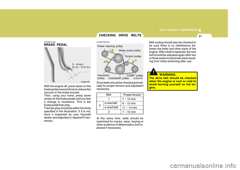
G170A01A-GAT BRAKE PEDAL
G160A01HR
3 ~ 8 mm (0.12 ~ 0.31 in.)
With the engine off, press down on the brake pedal several times to reduce thevacuum in the brake booster. Then, using your hand, press down slowly on the brake pedal until you feela change in resistance. This is the brake pedal free-play. The free-play should be within the limitsspecified in the illustration. If it is not, have it inspected by your Hyundai dealer and adjusted or repaired if nec-essary.
1
2
3
CHECKING DRIVE BELTS
Water pump pulley
G190A01HR-GAT
G190A01HR
Drive belts should be checked periodi- cally for proper tension and adjusted ifnecessary. Power steering pulley
Crankshaft pulley
Generator pulley Tension pulley
COMP. pulley
1
2 3
a new belt a used beltProper tension
7 ~ 10 mm9 ~ 12 mm11 ~ 14 mm7 ~ 10 mm
Belt
At the same time, belts should be examined for cracks, wear, fraying or other evidence of deterioration and re-placed if necessary.
!
Belt routing should also be checked to be sure there is no interference be-tween the belts and other parts of the engine. After a belt is replaced, the new belt should be adjusted again after twoor three weeks to eliminate slack result- ing from initial stretching after use. WARNING:
The drive belt should be checked when the engine is cool or cold to avoid burning yourself on hot en- gine.
Page 180 of 207
6 DO-IT-YOURSELF MAINTENANCE
22
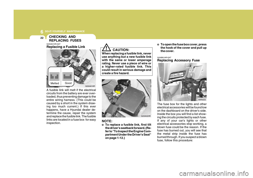
G200B01HR-GAT Replacing Accessory Fuse The fuse box for the lights and other electrical accessories will be found lowon the dashboard on the driver's side. Inside the box you will find a list show- ing the circuits protected by each fuse.If any of your car's lights or other electrical accessories stop working, a blown fuse could be the reason. If thefuse has burned out, you will see that the metal strip inside the fuse has burned through. If you suspect a blownfuse, follow this procedure: HHR4003
CHECKING AND REPLACING FUSES
CAUTION:
When replacing a fusible link, never use anything but a new fusible link with the same or lower amperagerating. Never use a piece of wire or a higher-rated fusible link. This could result in serious damage andcreate a fire hazard.
!
G200A01HR-GAT Replacing a Fusible Link
G200A01HR
Melted
Good
A fusible link will melt if the electrical circuits from the battery are ever over- loaded, thus preventing damage to the entire wiring harness. (This could becaused by a short in the system draw- ing too much current.) If this ever happens, have a Hyundai dealer de-termine the cause, repair the system and replace the fusible link. The fusible links are located in a fuse box for easyinspection. NOTE:
o To replace a fusible link, first tilt
the driver's seatback forward. (Re- fer to "To Inspect the Engine Com- partment Under the Driver's Seat" on page 1-12.) G200A02HRo To open the fuse box cover, press
the hook of the cover and pull upthe cover.
Page 182 of 207
6 DO-IT-YOURSELF MAINTENANCE
24
!
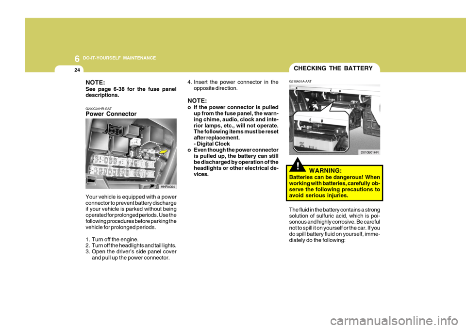
CHECKING THE BATTERY
G210A01A-AAT
WARNING:
Batteries can be dangerous! When working with batteries, carefully ob-serve the following precautions to avoid serious injuries. D010B01HR
The fluid in the battery contains a strong solution of sulfuric acid, which is poi- sonous and highly corrosive. Be careful not to spill it on yourself or the car. If youdo spill battery fluid on yourself, imme- diately do the following:
NOTE: See page 6-38 for the fuse panel descriptions. G200C01HR-GAT Power Connector
4. Insert the power connector in the
opposite direction.
NOTE:
o If the power connector is pulled up from the fuse panel, the warn- ing chime, audio, clock and inte-rior lamps, etc., will not operate. The following items must be reset after replacement.- Digital Clock
o Even though the power connector
is pulled up, the battery can stillbe discharged by operation of the headlights or other electrical de- vices.
Your vehicle is equipped with a powerconnector to prevent battery discharge if your vehicle is parked without being operated for prolonged periods. Use thefollowing procedures before parking the vehicle for prolonged periods.
1. Turn off the engine.
2. Turn off the headlights and tail lights.
3. Open the driver’s side panel cover and pull up the power connector.
HHR4004
Page 184 of 207
6 DO-IT-YOURSELF MAINTENANCE
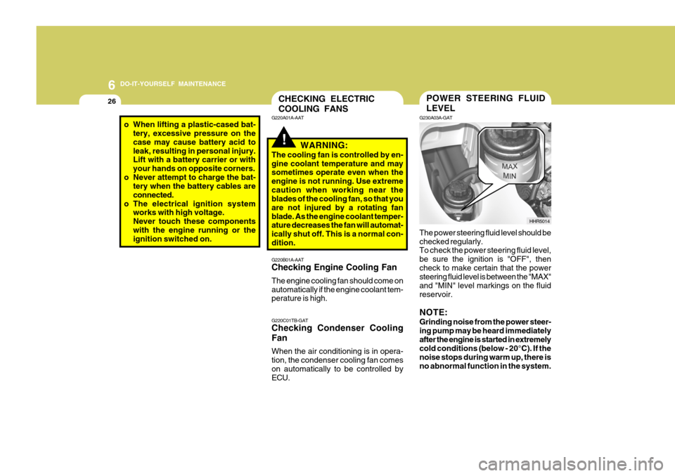
26POWER STEERING FLUID LEVEL
G230A03A-GAT The power steering fluid level should be checked regularly. To check the power steering fluid level, be sure the ignition is "OFF", thencheck to make certain that the power steering fluid level is between the "MAX" and "MIN" level markings on the fluidreservoir. NOTE: Grinding noise from the power steer- ing pump may be heard immediatelyafter the engine is started in extremely cold conditions (below - 20°C). If the noise stops during warm up, there isno abnormal function in the system. HHR5014CHECKING ELECTRIC COOLING FANS
!
G220B01A-AAT Checking Engine Cooling Fan The engine cooling fan should come on automatically if the engine coolant tem- perature is high. G220C01TB-GAT Checking Condenser Cooling Fan When the air conditioning is in opera- tion, the condenser cooling fan comeson automatically to be controlled by ECU.
G220A01A-AAT
WARNING:
The cooling fan is controlled by en- gine coolant temperature and may sometimes operate even when the engine is not running. Use extremecaution when working near the blades of the cooling fan, so that you are not injured by a rotating fanblade. As the engine coolant temper- ature decreases the fan will automat- ically shut off. This is a normal con-dition.
o When lifting a plastic-cased bat- tery, excessive pressure on the case may cause battery acid toleak, resulting in personal injury. Lift with a battery carrier or with your hands on opposite corners.
o Never attempt to charge the bat- tery when the battery cables areconnected.
o The electrical ignition system works with high voltage.Never touch these componentswith the engine running or the ignition switched on.
Page 185 of 207
6
DO-IT-YOURSELF MAINTENANCE
27
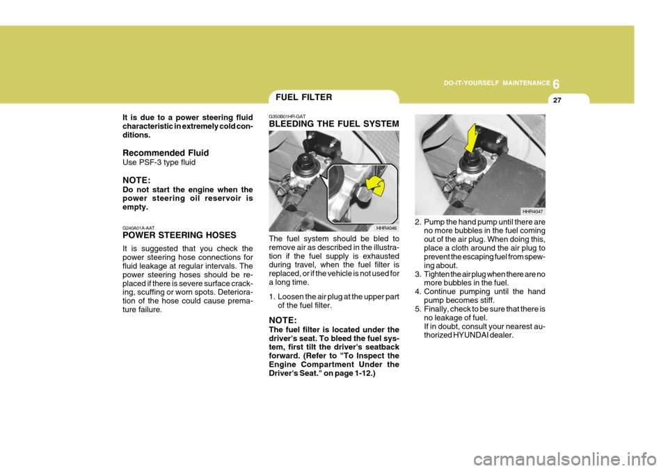
G350B01HR-GAT BLEEDING THE FUEL SYSTEM
The fuel system should be bled to remove air as described in the illustra-tion if the fuel supply is exhausted during travel, when the fuel filter is replaced, or if the vehicle is not used fora long time.
1. Loosen the air plug at the upper part of the fuel filter.
NOTE: The fuel filter is located under the driver's seat. To bleed the fuel sys- tem, first tilt the driver's seatback forward. (Refer to "To Inspect theEngine Compartment Under the Driver's Seat." on page 1-12.) HHR4046
2. Pump the hand pump until there are
no more bubbles in the fuel coming out of the air plug. When doing this,place a cloth around the air plug to prevent the escaping fuel from spew- ing about.
3. Tighten the air plug when there are no more bubbles in the fuel.
4. Continue pumping until the hand
pump becomes stiff.
5. Finally, check to be sure that there is
no leakage of fuel.If in doubt, consult your nearest au- thorized HYUNDAI dealer. HHR4047
FUEL FILTER
G240A01A-AAT POWER STEERING HOSES It is suggested that you check the power steering hose connections for fluid leakage at regular intervals. The power steering hoses should be re-placed if there is severe surface crack- ing, scuffing or worn spots. Deteriora- tion of the hose could cause prema-ture failure.
It is due to a power steering fluidcharacteristic in extremely cold con-ditions. Recommended Fluid Use PSF-3 type fluid NOTE: Do not start the engine when the power steering oil reservoir is empty.
Page 186 of 207
6 DO-IT-YOURSELF MAINTENANCE
28
!WARNING:
o Do not smoke or have any other open flame near the vehicle while bleeding the fuel system.
o Be sure to carefully clean away
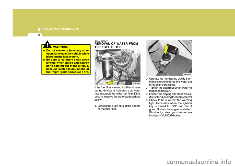
any fuel which spilled onto nearbyparts coming out of the air plug, because such accumulations of fuel might ignite and cause a fire. G300A01HR-GAT REMOVAL OF WATER FROM THE FUEL FILTER
HHR4045
If the fuel filter warning light illuminates during driving, it indicates that waterhas accumulated in the fuel filter. If this occurs, remove the water as described below.
1. Loosen the drain plug at the bottom of the fuel filter. HHR4047
2. Operate the hand pump slowly 6 or 7 times in order to force the water out through the drain plug.
3. Tighten the drain plug when water no longer comes out.
4. Loosen the air plug and bleed the air. (Refer to "Bleeding the fuel system")
5. Check to be sure that the warning
light illuminates when the ignition key is turned to "ON", and that it goes off when the engine is started. If in doubt, consult your nearest au-thorized HYUNDAI dealer.
Page 187 of 207
6
DO-IT-YOURSELF MAINTENANCE
29
!WARNING:
o Do not smoke or have any other open flame near the vehicle while bleeding the fuel system.
o Be sure to carefully wipe away any
water drained out in this manner,because the fuel mixed in the wa- ter might be ignited and result in a fire.
HEADLIGHT AIMING ADJUSTMENT
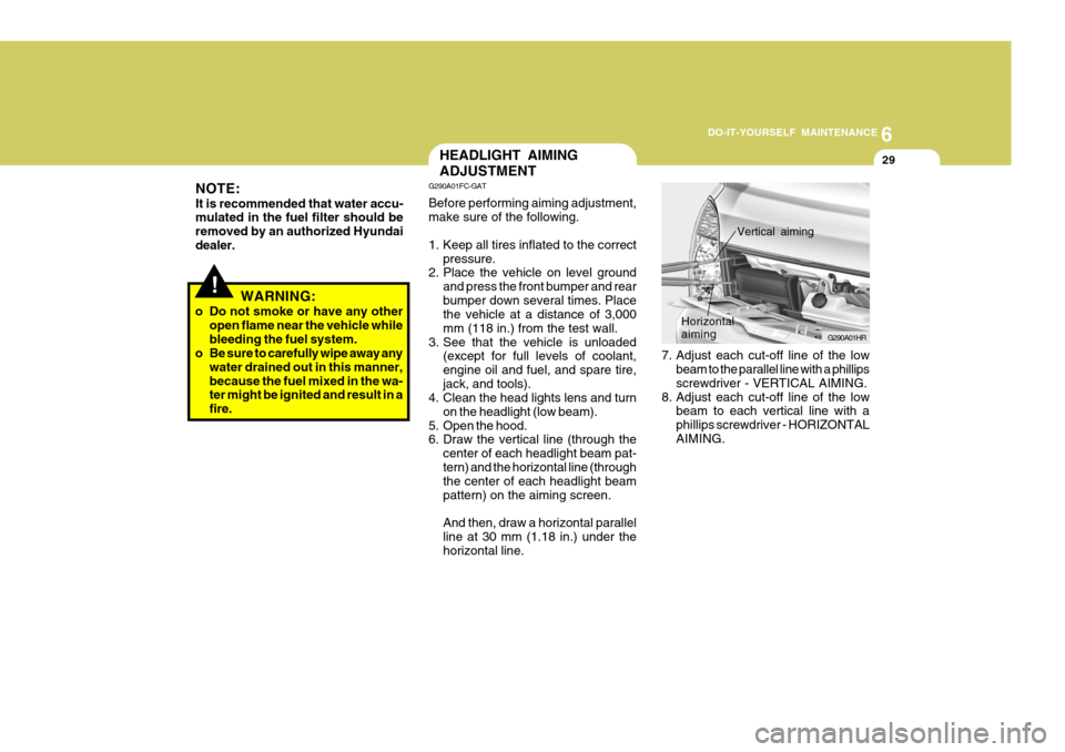
7. Adjust each cut-off line of the lowbeam to the parallel line with a phillips screwdriver - VERTICAL AIMING.
8. Adjust each cut-off line of the low beam to each vertical line with a phillips screwdriver - HORIZONTALAIMING. G290A01HR
Horizontal aiming
Vertical aiming
G290A01FC-GAT Before performing aiming adjustment, make sure of the following.
1. Keep all tires inflated to the correct
pressure.
2. Place the vehicle on level ground
and press the front bumper and rear bumper down several times. Place the vehicle at a distance of 3,000 mm (118 in.) from the test wall.
3. See that the vehicle is unloaded (except for full levels of coolant,engine oil and fuel, and spare tire,jack, and tools).
4. Clean the head lights lens and turn
on the headlight (low beam).
5. Open the hood.
6. Draw the vertical line (through the
center of each headlight beam pat- tern) and the horizontal line (through the center of each headlight beam pattern) on the aiming screen. And then, draw a horizontal parallel line at 30 mm (1.18 in.) under thehorizontal line.
NOTE: It is recommended that water accu- mulated in the fuel filter should be removed by an authorized Hyundaidealer.
Page 196 of 207
6 DO-IT-YOURSELF MAINTENANCE
38
BATT
GLOW IGN
ECU
BATT
LAMP
COND ABS2
PTC1 ABS1
PTC2
BLWR PTC3
FFHS
GLOW ALT_S STOP
HORN
A/CON TCU
ECU1 ECU2
DESCRIPTION
G200C01HR-GAT Engine Compartment
G200C02HR
NOTE:
Not all fuse panel descriptions in this manual may be applicable to your vehicle. It is accurate at the time of printing.
When you inspect the fuse box on your vehicle, refer to the fuse box label. AMPERAGES
100A80A 50A20A50A40A30A 30A40A 30A40A30A 40A 30A10A10A10A10A 10A 10A15A10A CIRCUIT PROTECTED
Generator Glow relay
Start relay, lgnition switchEngine control relay
I/P Fuse box (A/Con, Hazard, DR Lock), Power connector
P/WDW fusible link, Front Fog fuse, Tail lamp relayCondenser fan relayNot usedNot usedNot usedNot usedBlower relayNot usedNot usedECMGeneratorStop lamp switchHorn relayA/Con relayNot usedNot usedNot used
FUSIBLE LINK
FUSE
FUSE PANEL DESCRIPTION