Page 305 of 351
Installing a wheel cover
All models except Sport and CanadianLX model with manual transmission
1. Make sure the wire support ring is
hooked into the clips around the
edge of the wheel cover.
2. Align the valve mark on the wheelcover to the tire valve on the
wheel, then install the wheelcover.3. Make sure the wire support ring ison the outer side of the tire valve
as shown.CLIPS CLIPS
WIRE SUPPORT RING
Changing a Flat Tire
290
Table of Contents
Page 306 of 351

How to Use the Tire Repair Kit
All Canadian models with automatictransmission
To reduce weight, your vehicle is
equipped with a tire repair kit instead
of a spare tire. This kit will allow you
to temporarily repair a flat tire under
the following conditions:
● Only one tire is flat.
● The puncture is smaller than
3/16ths of an inch (4 mm).
● The puncture is located within the tread.
● The wheel rim is not damaged.
● The tire bead is seated.
When making a temporary repair,
carefully follow all instructions in this
owner's manual and in the
instructions that came with the kit. If you have a flat tire while driving,
park the vehicle on a level surface in
a safe place, put the transmission in
Park (P), set the parking brake, and
turn the hazard lights on.
Thoroughly examine the tire for a
puncture or other damage.
If a puncture is wider than 3/16ths of
an inch (4 mm), or is located in the
tire sidewall, do not attempt to repair
the tire. Have your vehicle towed to a
Honda service center. In Canada or
the continental U.S.A. simply call 1-
800-465-PLUS (7587) for Honda Plus
Roadside Assistance.
If the damage is smaller than 3/16ths
of an inch (4 mm) and within the tire
tread, proceed with the followinginstructions.
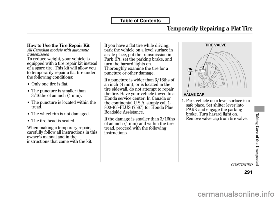
1. Park vehicle on a level surface in a
safe place. Set shifter lever into
PARK and engage the parking
brake. Turn hazard light on.
Remove valve cap from tire valve.
TIRE VALVE
VALVE CAP
CONTINUED
Temporarily Repairing a Flat Tire
291
Taking Care of the Unexpected
Table of Contents
Page 307 of 351
2. Open the tailgate.
3. Raise the cargo area floor lid bylifting it up with the back of the
strap. Remove the tire repair kit.Your tire repair kit contains:
● An air pump with a power cord and
an air hose attached.
● A bottle of sealant with a filler hoseattached.
● Two labels, one for the tire wheel
and one for the instrument panel.
● An instruction sheet. ●
An empty recovery bottle. A tire
repair professional will use this to
collect the injected sealant from the
tire during the permanent repair.
4. Remove the sealant bottle and
check the expiration date on the
label. If the date has expired, do not
continue. Have your vehicle towed
to the nearest Honda service
center. In Canada or the
continental U.S.A. simply call 1-800-
465-PLUS (7587) for Honda Plus
Roadside Assistance.
FLOOR LID
TIRE REPAIR KIT STRAP
EXPIRATION DATE
Temporarily Repairing a Flat Tire
292
Table of Contents
Page 310 of 351
14. Push the deflate button on the airpump until the air pressure gauge
shows 0 psi.15. Remove the wheel label from the repair kit, wipe any dirt off the
wheel with a clean cloth, and
attach the label to the center of thewheel.
The label may adhere poorly when
cold. Clean the surface and
securely attach the label.16. Remove the front pillar label fromthe repair kit and place it as shown above.
17. Remove the power plug from the accessory power socket.
18. Return all items except the air pump to the repair kit, and store
the kit in the cargo floor box. Keep
the air pump handy as you may
need it soon.
AIR PRESSURE GAUGE
DEFLATE BUTTON
WHEEL LABEL
LABEL
CONTINUED
Temporarily Repairing a Flat Tire
295
Taking Care of the Unexpected
Table of Contents
Page 320 of 351

U.S. Canada
Brake System
Indicator (Red)
The brake system indicator (red)
normally comes on when you turn
the ignition switch to the ON (II)
position, and as a reminder to check
the parking brake. It will stay on if
you do not fully release the parkingbrake.
If the brake system indicator (red)
comes on while driving, the brake
fluid level is probably low. Press
lightly on the brake pedal to see if it
feels normal. If it does, check the
brake fluid level the next time you
stop at a service station (see page261).
If the fluid level is low, take your
vehicle to a dealer, and have the
brake system inspected for leaks or
worn brake pads/shoes. However, if the brake pedal does not
feel normal, you should take
immediate action. A problem in one
part of the system's dual circuit
design will still give you braking at
two wheels. You will feel the brake
pedal go down much farther before
the vehicle begins to slow down, and
you will have to press harder on thepedal.
Slow down by shifting to a lower
gear, and pull to the side of the road
when it is safe. Because of the long
distance needed to stop, it is
hazardous to drive the vehicle. You
should have it towed and repaired as
soon as possible (see
Emergency
Towing on page 311).
If you must drive the vehicle a short
distance in this condition, drive
slowly and carefully. If the ABS indicator and the VSA
system indicator (if equipped) come
on with the brake system indicator,
have your vehicle inspected by your
dealer immediately.
Brake System Indicator
305
Taking Care of the Unexpected
Table of Contents
Page 326 of 351

If your vehicle needs to be towed,
call a professional towing service or
organization. Never tow your vehicle
with just a rope or chain. It is verydangerous.
There are two ways to tow your vehicle:
Flat-bed Equipment-The operator
loads your vehicle on the back of atruck. This is the best way to
transport your vehicle.
Wheel-lift Equipment- The tow
truck uses two pivoting arms that go
under the front tires and lift them off
the ground. The rear tires remain on
the ground. This is an acceptable
way to tow your vehicle. If, due to damage, your vehicle must
be towed with the front wheels on
the ground, do this:
Manual transmission:
●
Release the parking brake.
● Shift the transmission to neutral.
● Leave the ignition switch in the
ACCESSORY (I) position so the
steering wheel does not lock.
Automatic transmission:
●Release the parking brake.
● Start the engine.
● Shift to D position and hold for 5
seconds, then to N. Let the engine
run for 3 minutes, then turn it off.
● Turn off the engine.
● Leave the ignition switch in the
ACCESSORY (I) position so the
steering wheel does not lock.
Improper towing preparation will
damage the transmission. Follow the
above procedure exactly. If you cannot
shift the transmission or start the
engine (automatic transmission), your
vehicle must be transported with the
front wheels off the ground.
With the front wheels on the ground,
it is best to tow the vehicle no farther
than 50 miles (80 km), and keep the
speed below 35 mph (55 km/h).
CONTINUED
Emergency Towing
311
Taking Care of the Unexpected
Table of Contents
Page 327 of 351
Trying to lift or tow your vehicle by the
bumpers will cause serious damage.
The bumpers are not designed to
support the vehicle's weight.
The steering system can be damaged if
the steering wheel is locked. Leave the
ignition switch in the ACCESSORY (I)
position, and make sure the steering
wheel turns freely before you begin towing.If Your Vehicle Gets Stuck
If your vehicle gets stuck in sand,
mud, or snow, call a towing service to
pull it out (see page 311).
For very short distances, such as
freeing the vehicle, you can use the
detachable towing hook that mounts
on the anchor in the front bumper.
To use the towing hook:
1. Take the towing hook and the
extension out of the tool kit in the
cargo area.
2. Put a cloth on the notch of the cover. Using the extension,
carefully pry on the notch of the
cover to remove it.
Emergency Towing, If Your Vehicle Gets Stuck
312
Table of Contents
Page 333 of 351
DimensionsLength 161.6 in (4,105 mm) Width 66.7 in (1,695 mm)
Height 60.0 in (1,525 mm)
Wheelbase 98.4 in (2,500 mm)
Track Front 58.7 in (1,492 mm)
ꭧ 1
58.1 in (1,476 mm)ꭧ2
Rear 58.1 in (1,475 mm)ꭧ1
57.4 in (1,459 mm)ꭧ2
ꭧ 1: All models except Sport
ꭧ 2: Sport model
Weights Gross vehicle weight rating See the certification label attached to the driver's
doorjamb.
Seating Capacities Total 5
Front 2
Rear 3Engine
Type Water cooled 4-stroke SOHC i-VTEC 4-cylinder gasoline engine
Bore x Stroke 2.87 x 3.52 in (73.0 x 89.4 mm)
Displacement 91.3 cu-in (1,497 cm
3)
Compression ratio 10.4 : 1
Spark plugs IZFR6K13 (NGK)
SKJ20DR-M13 (DENSO)
Specifications
318
Table of Contents