2010 GMC SIERRA clock
[x] Cancel search: clockPage 546 of 630
Make sure that the jack head is positioned so that
the rear axle is resting securely between the
grooves that are on the jack head.
{WARNING:
Getting under a vehicle when it is jacked up is
dangerous. If the vehicle slips off the jack, you
could be badly injured or killed. Never get under a
vehicle when it is supported only by a jack.
{WARNING:
Raising your vehicle with the jack improperly
positioned can damage the vehicle and even
make the vehicle fall. To help avoid personal
injury and vehicle damage, be sure to fit the
jack lift head into the proper location before
raising the vehicle.
6. Turn the wheel wrench clockwise to raise the vehicle. Raise the vehicle far enough off the
ground so there is enough room for the spare tire
to fit under the wheel well.
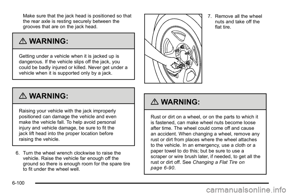
7. Remove all the wheelnuts and take off the
flat tire.
{WARNING:
Rust or dirt on a wheel, or on the parts to which it
is fastened, can make wheel nuts become loose
after time. The wheel could come off and cause
an accident. When changing a wheel, remove any
rust or dirt from places where the wheel attaches
to the vehicle. In an emergency, use a cloth or a
paper towel to do this; but be sure to use a
scraper or wire brush later, if needed, to get all the
rust or dirt off. See Changing a Flat Tire
on
page 6‑90
.
6-100
Page 547 of 630
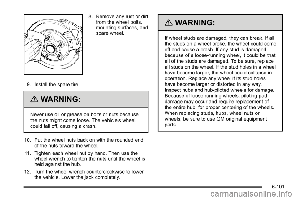
8. Remove any rust or dirtfrom the wheel bolts,
mounting surfaces, and
spare wheel.
9. Install the spare tire.
{WARNING:
Never use oil or grease on bolts or nuts because
the nuts might come loose. The vehicle's wheel
could fall off, causing a crash.
10. Put the wheel nuts back on with the rounded end of the nuts toward the wheel.
11. Tighten each wheel nut by hand. Then use the wheel wrench to tighten the nuts until the wheel is
held against the hub.
12. Turn the wheel wrench counterclockwise to lower the vehicle. Lower the jack completely.
{WARNING:
If wheel studs are damaged, they can break. If all
the studs on a wheel broke, the wheel could come
off and cause a crash. If any stud is damaged
because of a loose-running wheel, it could be that
all of the studs are damaged. To be sure, replace
all studs on the wheel. If the stud holes in a wheel
have become larger, the wheel could collapse in
operation. Replace any wheel if its stud holes
have become larger or distorted in any way.
Inspect hubs and hub‐piloted wheels for damage.
Because of loose running wheels, piloting pad
damage may occur and require replacement of
the entire hub, for proper centering of the wheels.
When replacing studs, hubs, wheel nuts or
wheels, be sure to use GM original equipment
parts.
6-101
Page 548 of 630
{WARNING:
Wheel nuts that are improperly or incorrectly
tightened can cause the wheels to become loose
or come off. The wheel nuts should be tightened
with a torque wrench to the proper torque
specification after replacing. Follow the torque
specification supplied by the aftermarket
manufacturer when using accessory locking wheel
nuts. SeeCapacities and Specifications
on
page 6‑126
for original equipment wheel nut
torque specifications.
Notice: Improperly tightened wheel nuts can lead
to brake pulsation and rotor damage. To avoid
expensive brake repairs, evenly tighten the wheel
nuts in the proper sequence and to the proper
torque specification. See Capacities and
Specifications
on page 6‑126for the wheel nut
torque specification.
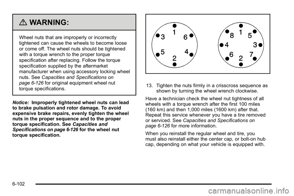
13. Tighten the nuts firmly in a crisscross sequence as
shown by turning the wheel wrench clockwise.
Have a technician check the wheel nut tightness of all
wheels with a torque wrench after the first 100 miles
(160 km) and then 1,000 miles (1600 km) after that.
Repeat this service whenever you have a tire removed
or serviced. See Capacities and Specifications
on
page 6‑126for more information.
When you reinstall the regular wheel and tire, you
must also reinstall either the center cap, or bolt-on hub
cap, depending on what your vehicle is equipped with.
6-102
Page 549 of 630
For center caps, place the cap on the wheel and tap it
into place until it seats flush with the wheel. The cap
only goes on one way. Be sure to line up the tab on
the center cap with the indentation on the wheel.
For bolt-on hub caps, align the plastic nut caps with the
wheel nuts and then tighten by hand. Then use the
wheel wrench to tighten.
Secondary Latch System
This vehicle may have an underbody-mounted tire hoist
assembly equipped with a secondary latch system. It is
designed to stop the spare tire from suddenly falling off
your vehicle. For the secondary latch to work, the spare
must be installed with the valve stem pointing down.
SeeStoring a Flat or Spare Tire and Tools
on
page 6‑106.
{WARNING:
Before beginning this procedure read all the
instructions. Failure to read and follow the
instructions could damage the hoist assembly and
you and others could get hurt. Read and follow
the instructions listed next. To release the spare tire from the secondary latch:
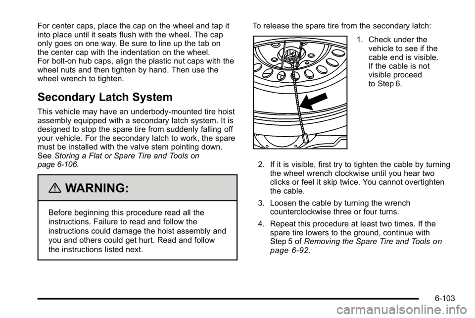
1. Check under the
vehicle to see if the
cable end is visible.
If the cable is not
visible proceed
to Step 6.
2. If it is visible, first try to tighten the cable by turning the wheel wrench clockwise until you hear two
clicks or feel it skip twice. You cannot overtighten
the cable.
3. Loosen the cable by turning the wrench counterclockwise three or four turns.
4. Repeat this procedure at least two times. If the spare tire lowers to the ground, continue with
Step 5 of Removing the Spare Tire and Tools
on
page 6‑92.
6-103
Page 550 of 630
5. If the spare does not lower, turn the wrenchcounterclockwise until approximately 6 inches
(15 cm) of cable is exposed.
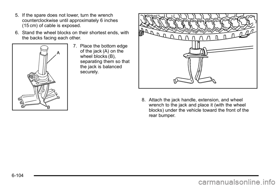
6. Stand the wheel blocks on their shortest ends, with the backs facing each other.
7. Place the bottom edgeof the jack (A) on the
wheel blocks (B),
separating them so that
the jack is balanced
securely.
8. Attach the jack handle, extension, and wheelwrench to the jack and place it (with the wheel
blocks) under the vehicle toward the front of the
rear bumper.
6-104
Page 551 of 630
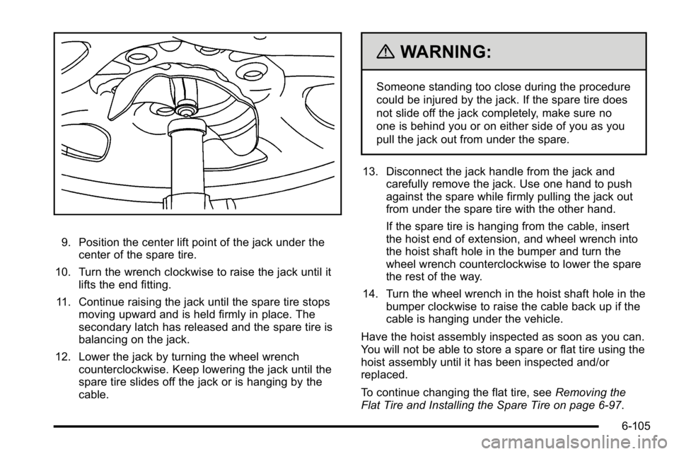
9. Position the center lift point of the jack under thecenter of the spare tire.
10. Turn the wrench clockwise to raise the jack until it lifts the end fitting.
11. Continue raising the jack until the spare tire stops moving upward and is held firmly in place. The
secondary latch has released and the spare tire is
balancing on the jack.
12. Lower the jack by turning the wheel wrench counterclockwise. Keep lowering the jack until the
spare tire slides off the jack or is hanging by the
cable.
{WARNING:
Someone standing too close during the procedure
could be injured by the jack. If the spare tire does
not slide off the jack completely, make sure no
one is behind you or on either side of you as you
pull the jack out from under the spare.
13. Disconnect the jack handle from the jack and carefully remove the jack. Use one hand to push
against the spare while firmly pulling the jack out
from under the spare tire with the other hand.
If the spare tire is hanging from the cable, insert
the hoist end of extension, and wheel wrench into
the hoist shaft hole in the bumper and turn the
wheel wrench counterclockwise to lower the spare
the rest of the way.
14. Turn the wheel wrench in the hoist shaft hole in the bumper clockwise to raise the cable back up if the
cable is hanging under the vehicle.
Have the hoist assembly inspected as soon as you can.
You will not be able to store a spare or flat tire using the
hoist assembly until it has been inspected and/or
replaced.
To continue changing the flat tire, see Removing the
Flat Tire and Installing the Spare Tire on page 6‑97.
6-105
Page 554 of 630
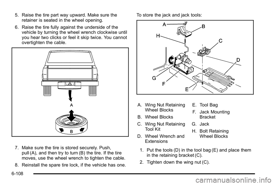
5. Raise the tire part way upward. Make sure theretainer is seated in the wheel opening.
6. Raise the tire fully against the underside of the vehicle by turning the wheel wrench clockwise until
you hear two clicks or feel it skip twice. You cannot
overtighten the cable.
7. Make sure the tire is stored securely. Push,pull (A), and then try to turn (B) the tire. If the tire
moves, use the wheel wrench to tighten the cable.
8. Reinstall the spare tire lock, if the vehicle has one. To store the jack and jack tools:
A. Wing Nut Retaining
Wheel Blocks
B. Wheel Blocks
C. Wing Nut Retaining Tool Kit
D. Wheel Wrench and Extensions E. Tool Bag
F. Jack Mounting Bracket
G. Jack H. Bolt Retaining Wheel Blocks
1. Put the tools (D) in the tool bag (E) and place them in the retaining bracket (C).
2. Tighten down the wing nut (C).
6-108
Page 616 of 630

Appearance Care (cont.)Sheet Metal Damage . . . . . . . . . . . . . . . . . . . . . . . . . . . . 6-116
Tires . . . . . . . . . . . . . . . . . . . . . . . . . . . . . . . . . . . . . . . . . . . . . 6-116
Underbody Maintenance . . . . . . . . . . . . . . . . . . . . . . . . . 6-116
Washing Your Vehicle . . . . . . . . . . . . . . . . . . . . . . . . . . . 6-113
Weatherstrips . . . . . . . . . . . . . . . . . . . . . . . . . . . . . . . . . . . . 6-113
Windshield and Wiper Blades . . . . . . . . . . . . . . . . . . . . 6-114
Ashtray . . . . . . . . . . . . . . . . . . . . . . . . . . . . . . . . . . . . . . . . . . . . 4-18
Assistance Program, Roadside . . . . . . . . . . . . . . . . . . . . . .8-7
Audio System . . . . . . . . . . . . . . . . . . . . . . . . . . . . . . . . . . . . . . 4-84 Audio Steering Wheel Controls . . . . . . . . . . . . . . . . . .4-145
Navigation/Radio System, see NavigationManual . . . . . . . . . . . . . . . . . . . . . . . . . . . . . . . . . . . . . . . . .4-123
Radio Reception . . . . . . . . . . . . . . . . . . . . . . . . . . . . . . . . .4-148
Rear Seat (RSA) . . . . . . . . . . . . . . . . . . . . . . . . . . . . . . . .4-143
Setting the Clock . . . . . . . . . . . . . . . . . . . . . . . . . . . . . . . . . 4-84
Theft-Deterrent Feature . . . . . . . . . . . . . . . . . . . . . . . . . .4-145
XM™ Satellite Radio Antenna System . . . . . . . . . . .4-149
Audio System(s) . . . . . . . . . . . . . . . . . . . . . . . . . . . . . . . . . . . 4-87
Automatic Headlamp System . . . . . . . . . . . . . . . . . . . . . . 4-12
Automatic Transmission Fluid . . . . . . . . . . . . . . . . . . . . . . . . . . . . . . . . . . . . . . . . 6-23, 6-26
Operation . . . . . . . . . . . . . . . . . . . . . . . . . . . . . . . . . . . . . . . . . 3-28
Auxiliary Roof Mounted Lamp . . . . . . . . . . . . . . . . . . . . . . . . . . . . . . 4-14
Axle, Rear . . . . . . . . . . . . . . . . . . . . . . . . . . . . . . . . . . . . . . . . . 6-48B
Battery . . . . . . . . . . . . . . . . . . . . . . . . . . . . . . . . . . . . . . . . . . . . 6-43 Electric Power Management . . . . . . . . . . . . . . . . . . . . . . 4-16
Run-Down Protection . . . . . . . . . . . . . . . . . . . . . . . . . . . . . 4-16
Belt Routing, Engine . . . . . . . . . . . . . . . . . . . . . . . . . . . . . . . 7-16
Bluetooth
®. . . . . . . . . . . . . . . . . . . . . . . . . . . . . . . . . . . . . . . . 4-123
Brake
Emergencies . . . . . . . . . . . . . . . . . . . . . . . . . . . . . . . . . . . . . . 5-5
Pedal and Adjustable Throttle . . . . . . . . . . . . . . . . . . . . 3-26
Brakes . . . . . . . . . . . . . . . . . . . . . . . . . . . . . . . . . . . . . . . . . . . . . 6-39 Antilock . . . . . . . . . . . . . . . . . . . . . . . . . . . . . . . . . . . . . . . . . . . . 5-4
Parking . . . . . . . . . . . . . . . . . . . . . . . . . . . . . . . . . . . . . . . . . . . 3-50
System Warning Light . . . . . . . . . . . . . . . . . . . . . . . . . . . . 4-39
Braking . . . . . . . . . . . . . . . . . . . . . . . . . . . . . . . . . . . . . . . . . . . . . .5-3
Braking in Emergencies . . . . . . . . . . . . . . . . . . . . . . . . . . . . .5-5
Break-In, New Vehicle . . . . . . . . . . . . . . . . . . . . . . . . . . . . . 3-21
Bulb Replacement . . . . . . . . . . . . . . . . . . . . . . . . . . . . . . . . . 6-62 Center High-Mounted Stoplamp (CHMSL) andCargo Lamp . . . . . . . . . . . . . . . . . . . . . . . . . . . . . . . . . . . . . 6-58
Fog Lamps . . . . . . . . . . . . . . . . . . . . . . . . . . . . . . . . . . . . . . . 4-13
Halogen Bulbs . . . . . . . . . . . . . . . . . . . . . . . . . . . . . . . . . . . . 6-57
Headlamp Aiming . . . . . . . . . . . . . . . . . . . . . . . . . . . . . . . . . 6-54
Headlamps . . . . . . . . . . . . . . . . . . . . . . . . . . . . . . . . . . . . . . . 6-57
i - 2