2010 GMC SIERRA ESP
[x] Cancel search: ESPPage 430 of 630

Weight‐Distributing Hitch Adjustment
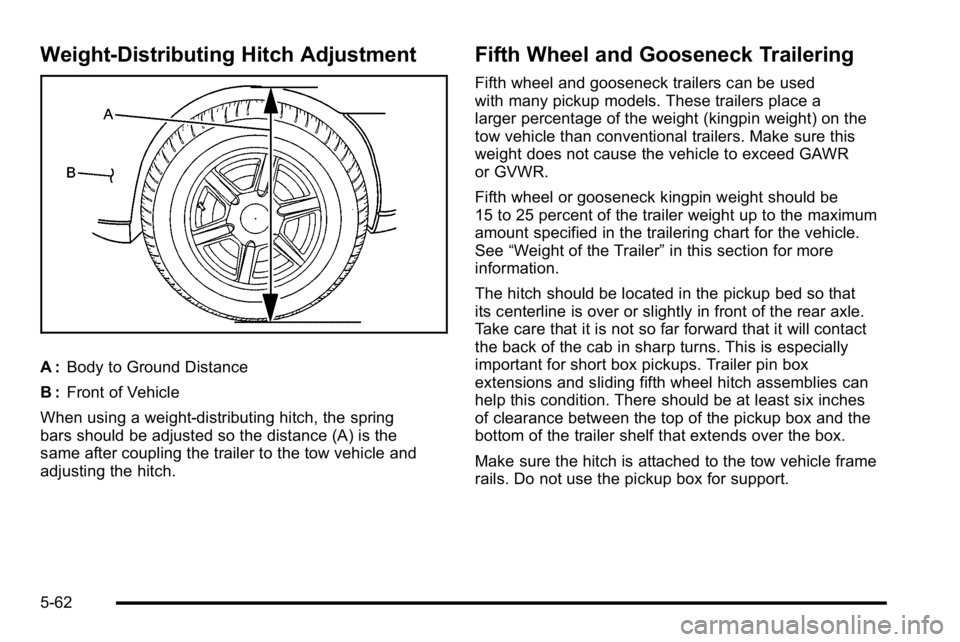
A :Body to Ground Distance
B : Front of Vehicle
When using a weight-distributing hitch, the spring
bars should be adjusted so the distance (A) is the
same after coupling the trailer to the tow vehicle and
adjusting the hitch.
Fifth Wheel and Gooseneck Trailering
Fifth wheel and gooseneck trailers can be used
with many pickup models. These trailers place a
larger percentage of the weight (kingpin weight) on the
tow vehicle than conventional trailers. Make sure this
weight does not cause the vehicle to exceed GAWR
or GVWR.
Fifth wheel or gooseneck kingpin weight should be
15 to 25 percent of the trailer weight up to the maximum
amount specified in the trailering chart for the vehicle.
See “Weight of the Trailer” in this section for more
information.
The hitch should be located in the pickup bed so that
its centerline is over or slightly in front of the rear axle.
Take care that it is not so far forward that it will contact
the back of the cab in sharp turns. This is especially
important for short box pickups. Trailer pin box
extensions and sliding fifth wheel hitch assemblies can
help this condition. There should be at least six inches
of clearance between the top of the pickup box and the
bottom of the trailer shelf that extends over the box.
Make sure the hitch is attached to the tow vehicle frame
rails. Do not use the pickup box for support.
5-62
Page 433 of 630

If the vehicle’s brake, anti‐lock brake or StabiliTrak
systems are not functioning properly, the ITBC system
may not be fully functional or may not function at all.
Make sure all of these systems are fully operational to
ensure full functionality of the ITBC system.
The ITBC system is powered through the vehicle's
electrical system. Turning the ignition off will also turn
off the ITBC system. The ITBC system is fully functional
only when the ignition is in ON or in RUN.
The ITBC system can only be used with trailers with
electric brakes.
{WARNING:
Connecting a trailer that is not compatible with the
ITBC system may result in reduced or complete
loss of trailer braking. There may be an increase
in stopping distance or trailer instability which
could result in personal injury or damage to the
vehicle, trailer, or other property. An aftermarket
controller may be available for use with trailers
with surge, air or electric‐over‐hydraulic trailer
brake systems. To determine the type of brakes
on the trailer and the availability of controllers,
check with your trailer manufacturer or
dealer/retailer.When trailering, make sure of the following:
.The ITBC system is used only with trailers that are
equipped with electric brakes.
.All applicable local and federal laws and
regulations are followed.
.All electrical and mechanical connections to the
trailer are made correctly.
.The trailer
’s brakes are in proper working
condition.
.The trailer and vehicle are properly loaded for the
towing condition.
The ITBC system is a factory installed item.
Out‐of‐factory installation of this system should
not be attempted. GM is not responsible for warranty
or performance of the system resulting from
out‐of‐factory installation.
5-65
Page 439 of 630

WARNING: (Continued)
To maximize safety when towing a trailer:
.Have the exhaust system inspected for leaks
and make necessary repairs before starting
a trip.
.Never drive with the liftgate, trunk/hatch,
or rear-most window open.
.Fully open the air outlets on or under the
instrument panel.
.Adjust the Climate Control system to a setting
that brings in only outside air and set the fan
speed to the highest setting. See Climate
Control System in the Index.
For more information about carbon monoxide, see
Engine Exhaust on page 3‑54.
Towing a trailer requires a certain amount of
experience. The combination you are driving is longer
and not as responsive as the vehicle itself. Get
acquainted with the handling and braking of the rig
before setting out for the open road. Before starting, check all trailer hitch parts and
attachments, safety chains, electrical connectors,
lamps, tires and mirrors. If the trailer has electric
brakes, start the combination moving and then apply the
trailer brake controller by hand to be sure the
brakes work.
During the trip, check occasionally to be sure that the
load is secure and the lamps and any trailer brakes
still work.
Following Distance
Stay at least twice as far behind the vehicle ahead as
you would when driving the vehicle without a trailer.
This can help to avoid heavy braking and sudden turns.
Passing
More passing distance is needed when towing a trailer.
The combination will not accelerate as quickly and is
longer so it is necessary to go much farther beyond the
passed vehicle before returning to the lane.
Backing Up
Hold the bottom of the steering wheel with one hand.
To move the trailer to the left, move that hand to the left.
To move the trailer to the right, move your hand to the
right. Always back up slowly and, if possible, have
someone guide you.
5-71
Page 442 of 630

Maintenance When Trailer Towing
The vehicle needs service more often when pulling a
trailer. See this manual's Maintenance Schedule or
Index for more information. Things that are especially
important in trailer operation are automatic transmission
fluid, engine oil, axle lubricant, belts, cooling system
and brake system. It is a good idea to inspect these
before and during the trip.
Check periodically to see that all hitch nuts and bolts
are tight.
Trailer Wiring Harness
The vehicle is equipped with one of the following wiring
harnesses for towing a trailer or hauling a slide-in
camper.
Basic Trailer Wiring
All regular, extended cab and crew cab pickups have a
seven‐wire trailer towing harness.
For vehicles not equipped with heavy duty trailering, the
harness is secured to the vehicle's frame behind the
spare tire mount. The harness requires the installation
of a trailer connector, which is available through your
dealer/retailer.
If towing a light‐duty trailer with a standard four‐way
round pin connector, an adapter is available from your
dealer/retailer.
Heavy-DutyTrailer Wiring Harness
Package
For vehicles equipped with heavy duty trailering, the
harness is connected to a bracket on the hitch platform.
The seven-wire harness contains the following trailer
circuits:
.Yellow: Left Stop/Turn Signal
.Dark Green: Right Stop/Turn Signal
.Brown: Taillamps
.White: Ground
.Light Green: Back-up Lamps
.Red: Battery Feed*
.Dark Blue: Trailer Brake*
5-74
Page 470 of 630

How to Check Automatic Transmission
Fluid
Because this operation can be a little difficult, you may
choose to have this done at the dealer/retailer service
department.
If you do it yourself, be sure to follow all the instructions
here or you could get a false reading on the dipstick.
Notice:Too much or too little fluid can damage your
transmission. Too much can mean that some of the
fluid could come out and fall on hot engine parts or
exhaust system parts, starting a fire. Too little fluid
could cause the transmission to overheat. Be sure
to get an accurate reading if you check your
transmission fluid.
Wait at least 30 minutes before checking the
transmission fluid level if you have been driving:
.When outside temperatures are above
32°C (90°F).
.At high speed for quite a while.
.In heavy traffic —especially in hot weather.
.While pulling a trailer.
To get the right reading, the fluid should be at
normal operating temperature, which is
82°C to 93°C (180°F to 200°F). Get the vehicle warmed up by driving about
24 km (15 miles) when outside temperatures are
above 10°C (50°F). If it is colder than 10°C (50°F), drive
the vehicle in 3 (Third) until the engine temperature
gage moves and then remains steady for 10 minutes.
A cold fluid check can be made after the vehicle has
been sitting for eight hours or more with the engine off,
but this is used only as a reference. Let the engine
run at idle for five minutes if outside temperatures are
10°C (50°F) or more. If it is colder than 10°C (50°F),
you may have to idle the engine longer. Should the fluid
level be low during this cold check, you must check the
fluid hot before adding fluid. Checking the fluid hot will
give you a more accurate reading of the fluid level.
Checking the Fluid Level
Prepare the vehicle as follows:
1. Park the vehicle on a level place. Keep the engine running.
2. With the parking brake applied, place the shift lever in P (Park).
3. With your foot on the brake pedal, move the shift lever through each gear range, pausing for about
three seconds in each range. Then, position the
shift lever in P (Park).
4. Let the engine run at idle for three minutes or more.
6-24
Page 490 of 630

Jump Starting
If the vehicle is a Two-mode Hybrid, see the Two-mode
Hybrid manual for more information.
If the vehicle's battery (or batteries) has run down, you
may want to use another vehicle and some jumper
cables to start your vehicle. Be sure to use the following
steps to do it safely.
{WARNING:
Batteries can hurt you. They can be dangerous
because:
.They contain acid that can burn you.
.They contain gas that can explode or ignite.
.They contain enough electricity to burn you.
If you do not follow these steps exactly, some or
all of these things can hurt you. Notice:
Ignoring these steps could result in costly
damage to the vehicle that would not be covered by
the warranty.
Trying to start the vehicle by pushing or pulling it
will not work, and it could damage the vehicle.
1. Check the other vehicle. It must have a 12-volt battery with a negative ground system.
Notice: If the other vehicle's system is not a 12-volt
system with a negative ground, both vehicles can
be damaged. Only use vehicles with 12-volt systems
with negative grounds to jump start your vehicle.
2. If you have a vehicle with a diesel engine with two batteries, you should know before you begin that,
especially in cold weather, you may not be able to
get enough power from a single battery in another
vehicle to start your diesel engine. If your vehicle
has more than one battery, using the battery
that is closer to the starter will reduce electrical
resistance. This is located on the passenger side,
in the rear of the engine compartment.
3. Get the vehicles close enough so the jumper cables can reach, but be sure the vehicles are not
touching each other. If they are, it could cause an
unwanted ground connection. You would not be
able to start your vehicle, and the bad grounding
could damage the electrical systems.
6-44
Page 517 of 630

Intended Outboard Sidewall:The side of an
asymmetrical tire, that must always face outward
when mounted on a vehicle.
Kilopascal (kPa)
:The metric unit for air
pressure.
Light Truck (LT‐Metric) Tire
:A tire used on light
duty trucks and some multipurpose passenger
vehicles.
Load Index
:An assigned number ranging from
1 to 279 that corresponds to the load carrying
capacity of a tire.
Maximum Inflation Pressure
:The maximum air
pressure to which a cold tire can be inflated. The
maximum air pressure is molded onto the
sidewall.
Maximum Load Rating
:The load rating for a tire
at the maximum permissible inflation pressure for
that tire.
Maximum Loaded Vehicle Weight
:The sum of
curb weight, accessory weight, vehicle capacity
weight, and production options weight.
Normal Occupant Weight
:The number of
occupants a vehicle is designed to seat multiplied
by 150 lbs (68 kg). See Loading the Vehicle
on
page 5‑30
. Occupant Distribution
:Designated seating
positions.
Outward Facing Sidewall
:The side of an
asymmetrical tire that has a particular side that
faces outward when mounted on a vehicle. The
side of the tire that contains a whitewall, bears
white lettering, or bears manufacturer, brand, and/
or model name molding that is higher or deeper
than the same moldings on the other sidewall of
the tire.
Passenger (P-Metric) Tire
:A tire used on
passenger cars and some light duty trucks and
multipurpose vehicles.
Recommended Inflation Pressure
:Vehicle
manufacturer's recommended tire inflation
pressure as shown on the tire placard. See
Inflation - Tire Pressure
on page 6‑72and Loading
the Vehicle
on page 5‑30.
Radial Ply Tire
:A pneumatic tire in which the ply
cords that extend to the beads are laid at
90 degrees to the centerline of the tread.
Rim
:A metal support for a tire and upon which
the tire beads are seated.
Sidewall
:The portion of a tire between the tread
and the bead.
6-71
Page 521 of 630

{WARNING:
If you operate your vehicle with a tire that is badly
underinflated, the tire can overheat. An
overheated tire can lose air suddenly or catch fire.
You or others could be injured. Be sure all tires
(including the spare) are properly inflated.
See Inflation - Tire Pressure
on page 6‑72, for
information on proper tire inflation.
Tire Pressure Monitor System
The Tire Pressure Monitor System (TPMS) uses radio
and sensor technology to check tire pressure levels.
The TPMS sensors monitor the air pressure in your
vehicle's tires and transmit tire pressure readings to a
receiver located in the vehicle.
Each tire, including the spare (if provided), should be
checked monthly when cold and inflated to the inflation
pressure recommended by the vehicle manufacturer
on the vehicle placard or tire inflation pressure label.
(If your vehicle has tires of a different size than the size
indicated on the vehicle placard or tire inflation pressure
label, you should determine the proper tire inflation
pressure for those tires.) As an added safety feature, your vehicle has been
equipped with a tire pressure monitoring system
(TPMS) that illuminates a low tire pressure telltale when
one or more of your tires is significantly under‐inflated.
Accordingly, when the low tire pressure telltale
illuminates, you should stop and check your tires as
soon as possible, and inflate them to the proper
pressure. Driving on a significantly under‐inflated tire
causes the tire to overheat and can lead to tire failure.
Under‐inflation also reduces fuel efficiency and tire
tread life, and may affect the vehicle's handling and
stopping ability.
Please note that the TPMS is not a substitute for proper
tire maintenance, and it is the driver's responsibility to
maintain correct tire pressure, even if under‐inflation
has not reached the level to trigger illumination of the
TPMS low tire pressure telltale.
Your vehicle has also been equipped with a TPMS
malfunction indicator to indicate when the system is
not operating properly. The TPMS malfunction indicator
is combined with the low tire pressure telltale. When
the system detects a malfunction, the telltale will
flash for approximately one minute and then remain
continuously illuminated. This sequence will continue
upon subsequent vehicle start‐ups as long as the
malfunction exists.
6-75