2010 GMC SIERRA engine
[x] Cancel search: enginePage 493 of 630

6. Check that the jumper cables do not have loose ormissing insulation. If they do, you could get a
shock. The vehicles could be damaged too.
Before you connect the cables, here are some
basic things you should know. Positive (+) will go to
positive (+) or to a remote positive (+) terminal if
the vehicle has one. Negative (−) will go to a
heavy, unpainted metal engine part or to a remote
negative (−) terminal if the vehicle has one.
Do not connect positive (+) to negative (−) or you
will get a short that would damage the battery and
maybe other parts too. And do not connect the
negative (−) cable to the negative (−) terminal on
the dead battery because this can cause sparks.
5.3L engine (4.3L, 4.8L,6.0L and 6.2L similar) 7. Connect the red
positive (+) cable to the
positive (+) terminal of
the vehicle with the
dead battery. 8. Do not let the other end touch metal. Connect it to
the positive (+) terminal of the good battery. Use a
remote positive (+) terminal if the vehicle has one.
9. Now connect the black negative (−) cable to the negative (−) terminal of the good battery. Use a
remote negative (−) terminal if the vehicle has one.
Do not let the other end touch anything until the
next step.
10. Connect the other end of the negative (−) cable to a heavy, unpainted metal engine part or to the
remote negative (−) terminal, on the vehicle with
the dead battery.
11. Start the vehicle with the good battery and run the engine for a while.
12. Try to start the vehicle that had the dead battery. If it will not start after a few tries, it probably
needs service.
6-47
Page 494 of 630

Notice:If the jumper cables are connected or
removed in the wrong order, electrical shorting may
occur and damage the vehicle. The repairs would
not be covered by the vehicle warranty. Always
connect and remove the jumper cables in the
correct order, making sure that the cables do
not touch each other or other metal.
Jumper Cable Removal
A. Heavy, Unpainted Metal Engine Part or Remote Negative (−) Terminal
B. Good Battery or Remote Positive (+) and Remote Negative (−) Terminals
C. Dead Battery or Remote Positive (+) Terminal To disconnect the jumper cables from both vehicles do
the following:
1. Disconnect the black negative (−) cable from the vehicle that had the bad battery.
2. Disconnect the black negative (−) cable from the vehicle with the good battery.
3. Disconnect the red positive (+) cable from the vehicle with the good battery.
4. Disconnect the red positive (+) cable from the other vehicle.
5. Return the positive (+) terminal cover, to its original position.
Rear Axle
When to Check Lubricant
It is not necessary to regularly check rear axle fluid
unless you suspect there is a leak or you hear an
unusual noise. A fluid loss could indicate a problem.
Have it inspected and repaired.
All axle assemblies are filled by volume of fluid during
production. They are not filled to reach a certain level.
When checking the fluid level on any axle, variations
in the readings can be caused by factory fill differences
between the minimum and the maximum fluid volume.
Also, if a vehicle has just been driven before checking
the fluid level, it may appear lower than normal because
6-48
Page 495 of 630

fluid has traveled out along the axle tubes and has not
drained back to the sump area. Therefore, a reading
taken five minutes after the vehicle has been driven will
appear to have a lower fluid level than a vehicle that
has been stationary for an hour or two. Remember that
the rear axle assembly must be supported to get a
true reading.
How to Check Lubricant
2500HD with 6.0L and 6.2L
All Other Series and Engines
To get an accurate reading, the vehicle should be on a
level surface.
.For all 4.3L, 4.8L and 5.3L 1500 Series
applications, the proper level is 0.04 inches to
0.75 inches (1.0 mm to 19.0 mm) below the bottom
of the filler hole, located on the rear axle. Add only
enough fluid to reach the proper level.
.For all 6.0L and 6.2L 1500 Series applications,
the proper level is from 0.6 inches to 1.6 inches
(15 mm to 40 mm) below the bottom of the filler
plug hole, located on the rear axle. Add only
enough fluid to reach the proper level.
6-49
Page 500 of 630

Federal law prohibits the following acts or the causing
thereof:1. The removal or rendering inoperative by any person, other than for purposes of maintenance,
repair or replacement, of any device or element of
design incorporated into any new vehicle for the
purpose of noise control, prior to its sale or delivery
to the ultimate purchaser or while it is in use; or
2. The use of the vehicle after such device or element of design has been removed or rendered
inoperative by any person.
Among those acts presumed to constitute tampering are
the acts listed below.
Insulation:
.Removal of the noise shields or any underhood
insulation.
Engine:
.Removal or rendering engine speed governor,
if the vehicle has one, inoperative so as to allow
engine speed to exceed manufacturer
specifications.
Fan and Drive:
.Removal of fan clutch, if the vehicle has one,
or rendering clutch inoperative.
.Removal of the fan shroud, if the vehicle has one.
Air Intake:
.Removal of the air cleaner silencer.
.Modification of the air cleaner.
Exhaust:
.Removal of the muffler and/or resonator.
.Removal of the exhaust pipes and exhaust pipe
clamps.
Headlamp Aiming
The vehicle has a visual optical headlamp aiming
system. The aim of the headlamps have been preset at
the factory and should need no further adjustment.
However, if the vehicle is damaged in a crash, the aim
of the headlamps may be affected and adjustment may
be necessary.
If oncoming vehicles flash their high beams at you, this
may mean the vertical aim of your headlamps needs to
be adjusted.
It is recommended that the vehicle is taken to your
dealer/retailer for service if the headlamps need to be
adjusted. It is possible however, to re-aim the
headlamps as described.
6-54
Page 503 of 630

9. Make sure that the light from the headlamp ispositioned at the bottom edge of the horizontal
tape line. The lamp on the left (A) shows the
correct headlamp aim. The lamp on the right (B)
shows the incorrect headlamp aim.
10. Repeat Steps 7 through 9 for the opposite headlamp.
Bulb Replacement
For the proper type of replacement bulbs, see
Replacement Bulbs on page 6‑62.
For any bulb changing procedure not listed in this
section, contact your dealer/retailer.
Halogen Bulbs
{WARNING:
Halogen bulbs have pressurized gas inside and
can burst if you drop or scratch the bulb. You or
others could be injured. Be sure to read and
follow the instructions on the bulb package.
Headlamps
To replace one of these bulbs:
1. Open the hood. See Hood Release
on page 6‑15for more information.
2. If you are replacing the bulb on the passenger side remove the Engine Air Cleaner cover. See Engine
Air Cleaner/Filter
on page 6‑21for more
information.
3. Reach in and access the bulb sockets from inside the engine compartment.
6-57
Page 514 of 630

(F) Tire Ply Material:The type of cord and
number of plies in the sidewall and under the
tread.
(G) Single Tire Maximum Load
:Maximum load
that can be carried and the maximum pressure
needed to support that load when used as a
single. For information on recommended tire
pressure see Inflation - Tire Pressure
on page 6‑72
andLoading the Vehicleon page 5‑30.
Tire Size
The following examples show the different parts of
a tire size.
Passenger (P‐Metric) Tire
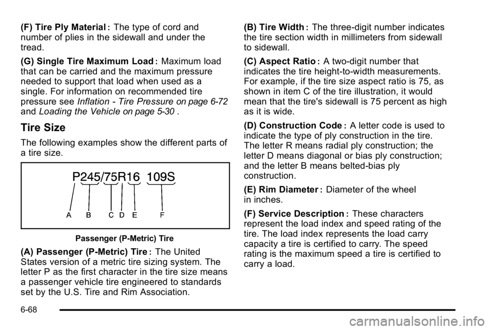
(A) Passenger (P‐Metric) Tire:The United
States version of a metric tire sizing system. The
letter P as the first character in the tire size means
a passenger vehicle tire engineered to standards
set by the U.S. Tire and Rim Association. (B) Tire Width
:The three‐digit number indicates
the tire section width in millimeters from sidewall
to sidewall.
(C) Aspect Ratio
:A two‐digit number that
indicates the tire height‐to‐width measurements.
For example, if the tire size aspect ratio is 75, as
shown in item C of the tire illustration, it would
mean that the tire's sidewall is 75 percent as high
as it is wide.
(D) Construction Code
:A letter code is used to
indicate the type of ply construction in the tire.
The letter R means radial ply construction; the
letter D means diagonal or bias ply construction;
and the letter B means belted‐bias ply
construction.
(E) Rim Diameter
:Diameter of the wheel
in inches.
(F) Service Description
:These characters
represent the load index and speed rating of the
tire. The load index represents the load carry
capacity a tire is certified to carry. The speed
rating is the maximum speed a tire is certified to
carry a load.
6-68
Page 515 of 630

Light Truck (LT‐Metric) Tire
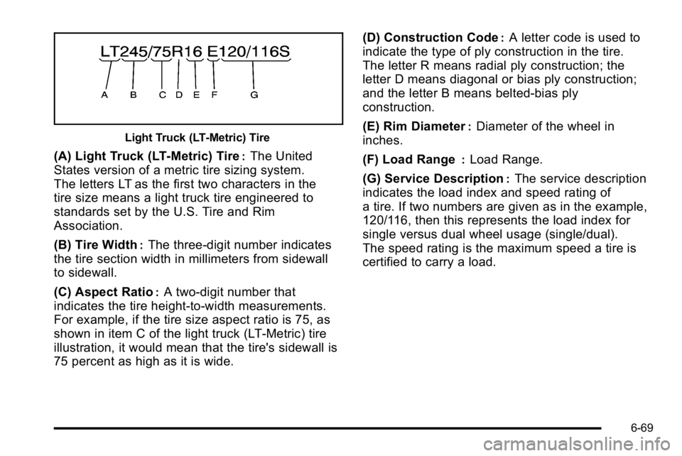
(A) Light Truck (LT‐Metric) Tire:The United
States version of a metric tire sizing system.
The letters LT as the first two characters in the
tire size means a light truck tire engineered to
standards set by the U.S. Tire and Rim
Association.
(B) Tire Width
:The three‐digit number indicates
the tire section width in millimeters from sidewall
to sidewall.
(C) Aspect Ratio
:A two‐digit number that
indicates the tire height‐to‐width measurements.
For example, if the tire size aspect ratio is 75, as
shown in item C of the light truck (LT‐Metric) tire
illustration, it would mean that the tire's sidewall is
75 percent as high as it is wide. (D) Construction Code
:A letter code is used to
indicate the type of ply construction in the tire.
The letter R means radial ply construction; the
letter D means diagonal or bias ply construction;
and the letter B means belted‐bias ply
construction.
(E) Rim Diameter
:Diameter of the wheel in
inches.
(F) Load Range
:Load Range.
(G) Service Description
:The service description
indicates the load index and speed rating of
a tire. If two numbers are given as in the example,
120/116, then this represents the load index for
single versus dual wheel usage (single/dual).
The speed rating is the maximum speed a tire is
certified to carry a load.
6-69
Page 525 of 630

The TPMS sensor matching process is outlined below:1. Set the parking brake.
2. Turn the ignition switch to ON/RUN with the engine off.
3. Press the Remote Keyless Entry (RKE) transmitter's LOCK and UNLOCK buttons at the
same time for approximately five seconds. The
horn sounds twice to signal the receiver is in
relearn mode and TIRE LEARNING ACTIVE
message displays on the DIC screen.
If your vehicle does not have RKE, press the
Driver Information Center (DIC) vehicle information
button until the PRESS
VTO RELEARN TIRE
POSITIONS message displays. The horn sounds
twice to signal the receiver is in relearn mode and
TIRE LEARNING ACTIVE message displays on
the DIC screen.
If your vehicle does not have RKE or DIC buttons,
press the trip odometer reset stem located on the
instrument panel cluster until the PRESS
VTO
RELEARN TIRE POSITIONS message displays.
The horn sounds twice to signal the receiver is in
relearn mode and TIRE LEARNING ACTIVE
message displays on the DIC screen.
4. Start with the driver side front tire. 5. Remove the valve cap from the valve cap stem.
Activate the TPMS sensor by increasing or
decreasing the tire's air pressure for five seconds,
or until a horn chirp sounds. The horn chirp, which
may take up to 30 seconds to sound, confirms that
the sensor identification code has been matched to
this tire and wheel position.
6. Proceed to the passenger side front tire, and repeat the procedure in Step 5.
7. Proceed to the passenger side rear tire, and repeat the procedure in Step 5.
8. Proceed to the driver side rear tire, and repeat the procedure in Step 5. The horn sounds two times to
indicate the sensor identification code has been
matched to the driver side rear tire, and that the
TPMS sensor matching process is no longer
active. The TIRE LEARNING ACTIVE message on
the DIC display screen goes off.
9. Turn the ignition switch to LOCK/OFF.
10. Set all four tires to the recommended air pressure level as indicated on the Tire and Loading
Information label.
11. Put the valve caps back on the valve stems.
6-79