2010 GMC SIERRA width
[x] Cancel search: widthPage 71 of 630
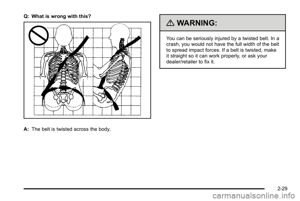
Q: What is wrong with this?
A:The belt is twisted across the body.
{WARNING:
You can be seriously injured by a twisted belt. In a
crash, you would not have the full width of the belt
to spread impact forces. If a belt is twisted, make
it straight so it can work properly, or ask your
dealer/retailer to fix it.
2-29
Page 388 of 630
Driving Across an Incline
An off-road trail will probably go across the incline of a
hill. To decide whether to try to drive across the incline,
consider the following:
{WARNING:
Driving across an incline that is too steep
will make your vehicle roll over. You could be
seriously injured or killed. If you have any doubt
about the steepness of the incline, do not drive
across it. Find another route instead.
.A hill that can be driven straight up or down
might be too steep to drive across. When going
straight up or down a hill, the length of the wheel
base—the distance from the front wheels to the
rear wheels —reduces the likelihood the vehicle
will tumble end over end. But when driving across
an incline, the narrower track width —the distance
between the left and right wheels —might not
prevent the vehicle from tilting and rolling over.
Driving across an incline puts more weight on the
downhill wheels which could cause a downhill slide
or a rollover.
.Surface conditions can be a problem. Loose
gravel, muddy spots, or even wet grass can cause
the tires to slip sideways, downhill. If the vehicle
slips sideways, it can hit something that will trip
it — a rock, a rut, etc. —and roll over.
.Hidden obstacles can make the steepness of the
incline even worse. If you drive across a rock with
the uphill wheels, or if the downhill wheels drop
into a rut or depression, the vehicle can tilt
even more.
For these reasons, carefully consider whether to try to
drive across an incline. Just because the trail goes
across the incline does not mean you have to drive it.
The last vehicle to try it might have rolled over.
If you feel the vehicle starting to slide sideways, turn
downhill. This should help straighten out the vehicle and
prevent the side slipping. The best way to prevent this
is to “walk the course” first, so you know what the
surface is like before driving it.
5-20
Page 403 of 630
{WARNING:
Things you put inside your vehicle can strike
and injure people in a sudden stop or turn,
or in a crash.
.Put things in the cargo area of your
vehicle. Try to spread the weight evenly.
.Never stack heavier things, like
suitcases, inside the vehicle so that some
of them are above the tops of the seats.
.Do not leave an unsecured child restraint
in your vehicle.
.When you carry something inside the
vehicle, secure it whenever you can.
.Do not leave a seat folded down unless
you need to.
There is also important loading information for
off-road driving in this manual. See “Loading Your
Vehicle for Off-Road Driving“ underOff-Road
Driving
on page 5‑11.
Two-Tiered Loading
Depending on the model of your pick‐up, you
can create an upper load platform by positioning
two or four 2 inches (5 cm) by 6 inches (15 cm)
wooden planks across the width of the pickup box.
The planks must be inserted in the pickup box
depressions. The length of the planks must allow
for at least a 3/4 inch (2 cm) bearing surface on
each end of the plank.
When using this upper load platform, be sure
the load is securely tied down to prevent it from
shifting. The load's center of gravity should be
positioned in a zone over the rear axle. The zone
is located in the area between the front of each
wheel well and the rear of each wheel well. The
center of gravity height must not extend above the
top of the pickup box flareboard.
Any load that extends beyond the vehicle's
taillamp area must be properly marked according
to local laws and regulations.
Remember not to exceed the Gross Axle Weight
Rating (GAWR) of the front or rear axle.
5-35
Page 502 of 630

4. At a wall, measure from the ground upward (A) tothe recorded distance from Step 3 and mark it.
5. Draw or tape a horizontal line (B) on the wall the width of the vehicle at the height of the mark
in Step 4.
Notice: Do not cover a headlamp to improve beam
cut-off when aiming. Covering a headlamp may
cause excessive heat build-up which may cause
damage to the headlamp.
6. Turn on the low-beam headlamps and place a piece of cardboard or equivalent in front of the
headlamp not being adjusted. This allows only the
beam of light from the headlamp being adjusted to
be seen on the flat surface.
7. Locate the vertical headlamp aiming screws, whichare under the hood near each headlamp assembly.
The adjustment screw can be turned with an
E8 Torx
®socket.
8. Turn the vertical aiming screw until the headlamp beam is aimed to the horizontal tape line. Turn it
clockwise or counterclockwise to raise or lower
the angle of the beam.
6-56
Page 511 of 630
Notice:If the vehicle has low‐profile tires, they
are more susceptible to damage from road
hazards or curb impact than standard profile
tires. Tire and/or wheel assembly damage can
occur when coming into contact with road
hazards like, potholes, or sharp edged objects,
or when sliding into a curb. The vehicle
warranty does not cover this type of damage.
Keep tires set to the correct inflation pressure
and, when possible avoid contact with curbs,
potholes, and other road hazards.
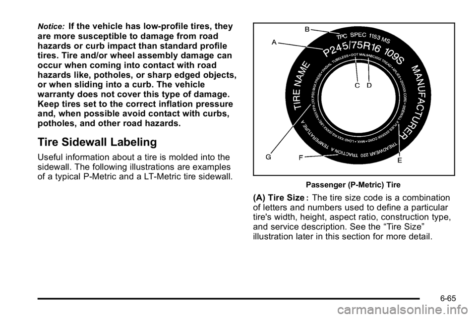
Tire Sidewall Labeling
Useful information about a tire is molded into the
sidewall. The following illustrations are examples
of a typical P‐Metric and a LT‐Metric tire sidewall.
Passenger (P‐Metric) Tire
(A) Tire Size:The tire size code is a combination
of letters and numbers used to define a particular
tire's width, height, aspect ratio, construction type,
and service description. See the “Tire Size”
illustration later in this section for more detail.
6-65
Page 513 of 630
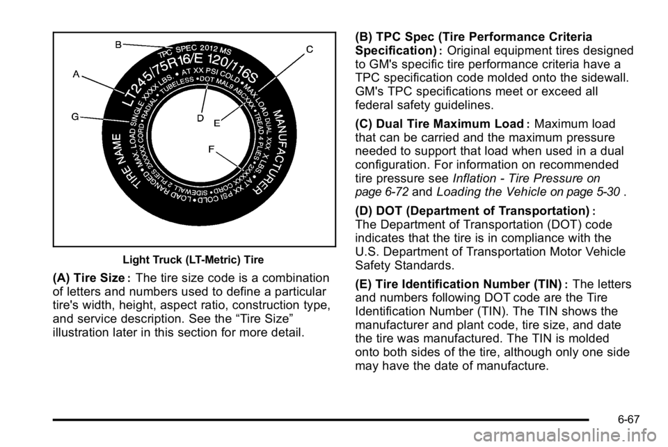
Light Truck (LT-Metric) Tire
(A) Tire Size:The tire size code is a combination
of letters and numbers used to define a particular
tire's width, height, aspect ratio, construction type,
and service description. See the “Tire Size”
illustration later in this section for more detail. (B) TPC Spec (Tire Performance Criteria
Specification)
:Original equipment tires designed
to GM's specific tire performance criteria have a
TPC specification code molded onto the sidewall.
GM's TPC specifications meet or exceed all
federal safety guidelines.
(C) Dual Tire Maximum Load
:Maximum load
that can be carried and the maximum pressure
needed to support that load when used in a dual
configuration. For information on recommended
tire pressure see Inflation - Tire Pressure
on
page 6‑72
and Loading the Vehicleon page 5‑30.
(D) DOT (Department of Transportation)
:
The Department of Transportation (DOT) code
indicates that the tire is in compliance with the
U.S. Department of Transportation Motor Vehicle
Safety Standards.
(E) Tire Identification Number (TIN)
:The letters
and numbers following DOT code are the Tire
Identification Number (TIN). The TIN shows the
manufacturer and plant code, tire size, and date
the tire was manufactured. The TIN is molded
onto both sides of the tire, although only one side
may have the date of manufacture.
6-67
Page 514 of 630
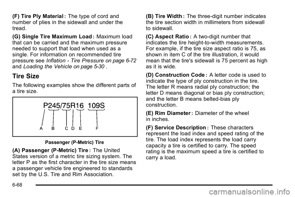
(F) Tire Ply Material:The type of cord and
number of plies in the sidewall and under the
tread.
(G) Single Tire Maximum Load
:Maximum load
that can be carried and the maximum pressure
needed to support that load when used as a
single. For information on recommended tire
pressure see Inflation - Tire Pressure
on page 6‑72
andLoading the Vehicleon page 5‑30.
Tire Size
The following examples show the different parts of
a tire size.
Passenger (P‐Metric) Tire
(A) Passenger (P‐Metric) Tire:The United
States version of a metric tire sizing system. The
letter P as the first character in the tire size means
a passenger vehicle tire engineered to standards
set by the U.S. Tire and Rim Association. (B) Tire Width
:The three‐digit number indicates
the tire section width in millimeters from sidewall
to sidewall.
(C) Aspect Ratio
:A two‐digit number that
indicates the tire height‐to‐width measurements.
For example, if the tire size aspect ratio is 75, as
shown in item C of the tire illustration, it would
mean that the tire's sidewall is 75 percent as high
as it is wide.
(D) Construction Code
:A letter code is used to
indicate the type of ply construction in the tire.
The letter R means radial ply construction; the
letter D means diagonal or bias ply construction;
and the letter B means belted‐bias ply
construction.
(E) Rim Diameter
:Diameter of the wheel
in inches.
(F) Service Description
:These characters
represent the load index and speed rating of the
tire. The load index represents the load carry
capacity a tire is certified to carry. The speed
rating is the maximum speed a tire is certified to
carry a load.
6-68
Page 515 of 630
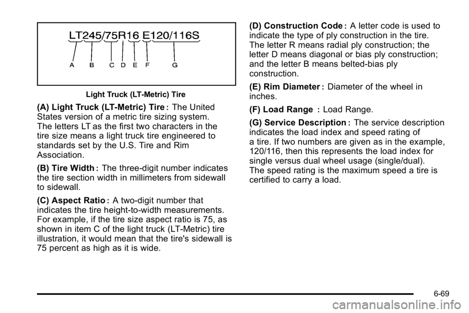
Light Truck (LT‐Metric) Tire
(A) Light Truck (LT‐Metric) Tire:The United
States version of a metric tire sizing system.
The letters LT as the first two characters in the
tire size means a light truck tire engineered to
standards set by the U.S. Tire and Rim
Association.
(B) Tire Width
:The three‐digit number indicates
the tire section width in millimeters from sidewall
to sidewall.
(C) Aspect Ratio
:A two‐digit number that
indicates the tire height‐to‐width measurements.
For example, if the tire size aspect ratio is 75, as
shown in item C of the light truck (LT‐Metric) tire
illustration, it would mean that the tire's sidewall is
75 percent as high as it is wide. (D) Construction Code
:A letter code is used to
indicate the type of ply construction in the tire.
The letter R means radial ply construction; the
letter D means diagonal or bias ply construction;
and the letter B means belted‐bias ply
construction.
(E) Rim Diameter
:Diameter of the wheel in
inches.
(F) Load Range
:Load Range.
(G) Service Description
:The service description
indicates the load index and speed rating of
a tire. If two numbers are given as in the example,
120/116, then this represents the load index for
single versus dual wheel usage (single/dual).
The speed rating is the maximum speed a tire is
certified to carry a load.
6-69