Page 416 of 550
Brake Wear
This vehicle has front disc brakes and could have rear
drum brakes or rear disc brakes.
Disc brake pads have built-in wear indicators that make
a high-pitched warning sound when the brake pads are
worn and new pads are needed. The sound can come
and go or be heard all the time the vehicle is moving,
except when applying the brake pedal firmly.
{WARNING:
The brake wear warning sound means that soon
the brakes will not work well. That could lead to
an accident. When the brake wear warning sound
is heard, have the vehicle serviced.
Notice: Continuing to drive with worn-out brake
pads could result in costly brake repair.
Some driving conditions or climates can cause a brake
squeal when the brakes are first applied or lightly
applied. This does not mean something is wrong with
the brakes. Properly torqued wheel nuts are necessary to help
prevent brake pulsation. When tires are rotated, inspect
brake pads for wear and evenly tighten wheel nuts in
the proper sequence to torque specifications in
Capacities and Specifications on page 6‑122.
If the vehicle has rear drum brakes, they do not have
wear indicators, but if a rear brake rubbing noise is
heard, have the rear brake linings inspected
immediately. Rear brake drums should be removed and
inspected each time the tires are removed for rotation or
changing. Drum brakes have an inspection hole to
inspect lining wear during scheduled maintenance.
When the front brake pads are replaced, have the rear
brakes inspected, too.
Brake linings should always be replaced as complete
axle sets.
Brake Pedal Travel
See your dealer/retailer if the brake pedal does not
return to normal height, or if there is a rapid increase in
pedal travel. This could be a sign that brake service
might be required.
Brake Adjustment
Every brake stop, the brakes adjust for wear.
6-42
Page 419 of 550
Notice:If you leave the radio or other accessories
on during the jump starting procedure, they could
be damaged. The repairs would not be covered by
the warranty. Always turn off the radio and other
accessories when jump starting the vehicle.
3. Turn off the ignition on both vehicles. Unplug unnecessary accessories plugged into the
cigarette lighter or the accessory power outlets.
Turn off the radio and all the lamps that are not
needed. This avoids sparks and helps save both
batteries. And it could save the radio!
4. Open the hood on the other vehicle and locate the positive (+) and negative (−) terminal locations on
that vehicle.
Your vehicle has a remote positive (+) jump starting
terminal and a remote negative (−) jump starting
terminal. You should always use these remote
terminals instead of the terminals on the battery.
If the vehicle has a remote positive (+) terminal, it
is located under a red plastic cover at the positive
battery post. To uncover the remote positive (+)
terminal, open the red plastic cover.
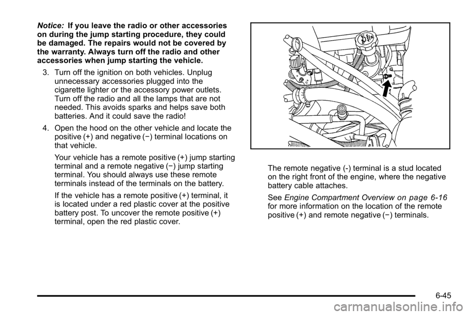
The remote negative (-) terminal is a stud located
on the right front of the engine, where the negative
battery cable attaches.
See Engine Compartment Overview
on page 6‑16for more information on the location of the remote
positive (+) and remote negative (−) terminals.
6-45
Page 420 of 550
{WARNING:
An electric fan can start up even when the engine
is not running and can injure you. Keep hands,
clothing and tools away from any underhood
electric fan.
{WARNING:
Using an open flame near a battery can cause
battery gas to explode. People have been hurt
doing this, and some have been blinded. Use a
flashlight if you need more light.
Be sure the battery has enough water. You do not
need to add water to the battery installed in your
new vehicle. But if a battery has filler caps, be
sure the right amount of fluid is there. If it is low,
add water to take care of that first. If you do not,
explosive gas could be present.
Battery fluid contains acid that can burn you. Do
not get it on you. If you accidentally get it in your
eyes or on your skin, flush the place with water
and get medical help immediately.
{WARNING:
Fans or other moving engine parts can injure you
badly. Keep your hands away from moving parts
once the engine is running.
5. Check that the jumper cables do not have loose or missing insulation. If they do, you could get a
shock. The vehicles could be damaged too.
Before you connect the cables, here are some
basic things you should know. Positive (+) will go to
positive (+) or to a remote positive (+) terminal if
the vehicle has one. Negative (−) will go to a
heavy, unpainted metal engine part or to a remote
negative (−) terminal if the vehicle has one.
Do not connect positive (+) to negative (−) or you
will get a short that would damage the battery and
maybe other parts too. And do not connect the
negative (−) cable to the negative (−) terminal on
the dead battery because this can cause sparks.
6-46
Page 426 of 550
Headlamp Aiming
The vehicle has a visual optical headlamp aiming
system. The aim of the headlamps have been preset at
the factory and should need no further adjustment.
However, if the vehicle is damaged in a crash, the aim
of the headlamps may be affected and adjustment may
be necessary.
If oncoming vehicles flash their high beams at you, this
may mean the vertical aim of your headlamps needs to
be adjusted.
It is recommended that the vehicle is taken to your
dealer/retailer for service if the headlamps need to be
adjusted. It is possible however, to re-aim the
headlamps as described.The vehicle should:.Be placed so the headlamps are 25 ft. (7.6 m) from
a light colored wall.
.Have all four tires on a level surface which is level
all the way to the wall.
.Be placed so it is perpendicular to the wall.
.Not have any snow, ice, or mud on it.
.Be fully assembled and all other work stopped
while headlamp aiming is being performed.
.Normally loaded with a full tank of fuel and one
person or 160 lbs (75 kg) sitting on the driver seat.
.Have the tires properly inflated.
.Have the spare tire is in its proper location in the
vehicle.
6-52
Page 427 of 550
Headlamp aiming is done with the vehicle's low-beam
headlamps. The high-beam headlamps will be correctly
aimed if the low-beam headlamps are aimed properly.
To adjust the vertical aim:1. Open the hood. See Hood Release on page 6‑14
2. Locate the aim dot on the lens of the low‐beam
headlamp.
3. Record the distance from the ground to the aim dot on the low‐beam headlamp.
4. At a wall, measure from the ground upward (A) tothe recorded distance from Step 3 and mark it.
5. Draw or tape a horizontal line (B) on the wall the width of the vehicle at the height of the mark in
Step 4.
Notice: Do not cover a headlamp to improve beam
cut-off when aiming. Covering a headlamp may
cause excessive heat build-up which may cause
damage to the headlamp.
6. Turn on the low-beam headlamps and place a piece of cardboard or equivalent in front of the
headlamp not being adjusted. This allows only the
beam of light from the headlamp being adjusted to
be seen on the flat surface.
6-53
Page 428 of 550
7. Locate the vertical headlamp aiming screws, whichare under the hood near each headlamp assembly.
The adjustment screw can be turned with an
E8 Torx
®socket.
8. Turn the vertical aiming screw until the headlamp beam is aimed to the horizontal tape line. Turn it
clockwise or counterclockwise to raise or lower the
angle of the beam.
9. Make sure that the light from the headlamp is
positioned at the bottom edge of the horizontal
tape line. The lamp on the left (A) shows the
correct headlamp aim. The lamp on the right (B)
shows the incorrect headlamp aim.
10. Repeat Steps 7 through 9 for the opposite headlamp.
6-54
Page 434 of 550
License Plate Lamp
To replace one of these bulbs:1. Reach under the rear bumper for the bulb socket.
2. Turn the bulb socket counterclockwise and pull the bulb socket out of the connector.
3. Pull the old bulb from the bulb socket, keeping the bulb straight as you pull it out.
4. Install the new bulb.
5. Reverse Steps 1 through 3 to reinstall the bulb socket.
Replacement Bulbs
Exterior Lamp Bulb Number
Back-up Lamp 3047 or 921
Center High-Mounted Stoplight (CHMSL), Cargo Lamp 912
Front Turn Signal Lamp, Sidemarker
Lamp and Parking Lamp 3157A
High-Beam Headlamp 9005
Low-Beam Headlamp H11
License Plate Lamp 168
Rear Turn Signal Lamp, Taillamp, and
Stoplamp 3047
Sidemarker Lamp 194
For replacement bulbs not listed here, contact your
dealer/retailer.
6-60
Page 439 of 550
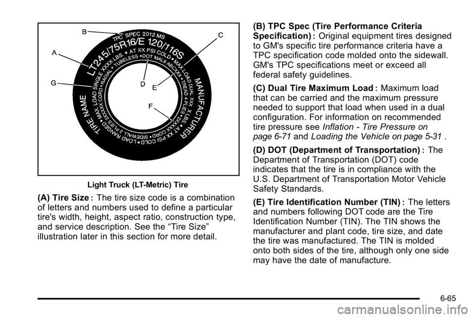
Light Truck (LT-Metric) Tire
(A) Tire Size:The tire size code is a combination
of letters and numbers used to define a particular
tire's width, height, aspect ratio, construction type,
and service description. See the “Tire Size”
illustration later in this section for more detail. (B) TPC Spec (Tire Performance Criteria
Specification)
:Original equipment tires designed
to GM's specific tire performance criteria have a
TPC specification code molded onto the sidewall.
GM's TPC specifications meet or exceed all
federal safety guidelines.
(C) Dual Tire Maximum Load
:Maximum load
that can be carried and the maximum pressure
needed to support that load when used in a dual
configuration. For information on recommended
tire pressure see Inflation - Tire Pressure
on
page 6‑71
and Loading the Vehicleon page 5‑31.
(D) DOT (Department of Transportation)
:The
Department of Transportation (DOT) code
indicates that the tire is in compliance with the
U.S. Department of Transportation Motor Vehicle
Safety Standards.
(E) Tire Identification Number (TIN)
:The letters
and numbers following DOT code are the Tire
Identification Number (TIN). The TIN shows the
manufacturer and plant code, tire size, and date
the tire was manufactured. The TIN is molded
onto both sides of the tire, although only one side
may have the date of manufacture.
6-65