Page 314 of 424
4. Turn the bulb clockwise one quarter turn to install it
in the socket.
5. Reinstall the CHMSL assembly and two screws.
Do not block or damage the CHMSL when items
are loaded on the roof of the vehicle.
Taillamps
To replace one of these bulbs:
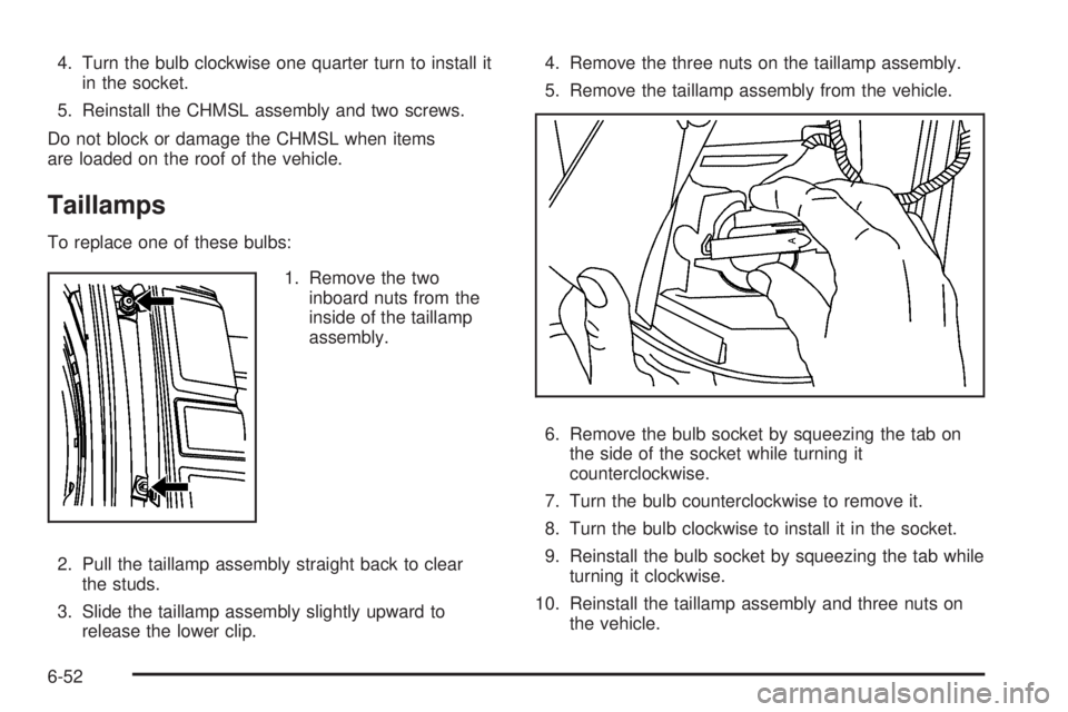
1. Remove the two
inboard nuts from the
inside of the taillamp
assembly.
2. Pull the taillamp assembly straight back to clear
the studs.
3. Slide the taillamp assembly slightly upward to
release the lower clip.4. Remove the three nuts on the taillamp assembly.
5. Remove the taillamp assembly from the vehicle.
6. Remove the bulb socket by squeezing the tab on
the side of the socket while turning it
counterclockwise.
7. Turn the bulb counterclockwise to remove it.
8. Turn the bulb clockwise to install it in the socket.
9. Reinstall the bulb socket by squeezing the tab while
turning it clockwise.
10. Reinstall the taillamp assembly and three nuts on
the vehicle.
6-52
Page 315 of 424
11. Slide the taillamp slightly downward to reengage
the lower clip.
12. Push the taillamp straight forward to reengage
the studs.
13. Reinstall the two inboard nuts from the inside of the
taillamp assembly.
License Plate Lamp
To replace one of these bulbs:
A. Bulb Socket
B. License Plate Bulb Assembly
C. Screws1. Remove the two screws (C) securing the license
plate bulb assembly (B).
2. Turn the bulb socket (A) counterclockwise and pull
the bulb straight out of the socket.
3. Install the new bulb.
4. Reverse steps 1 and 2 to reinstall the license plate
bulb assembly.Replacement Bulbs
Exterior Lamp Bulb Number
Back-up, Rear Parking,
Stoplamp, and Turn Signal Lamp3157
Center High Mounted Stop
Lamp (CHMSL)912
Front Parking and Turn
Signal Lamp3157KX
Front Sidemarker Lamp 194
License Plate Lamp 194
Headlamps
Composite High-Beam
Headlamp9005
Composite Low-Beam
Headlamp9006GS
Sealed Beam Headlamp H6054
For replacement bulbs not listed here, contact your
dealer/retailer.
6-53
Page 316 of 424
Windshield Wiper Blade
Replacement
Windshield wiper blades should be inspected for wear
and cracking. SeeScheduled Maintenance on page 7-3
for more information on wiper blade inspection.
Replacement blades come in different types and are
removed in different ways. To remove the type with a
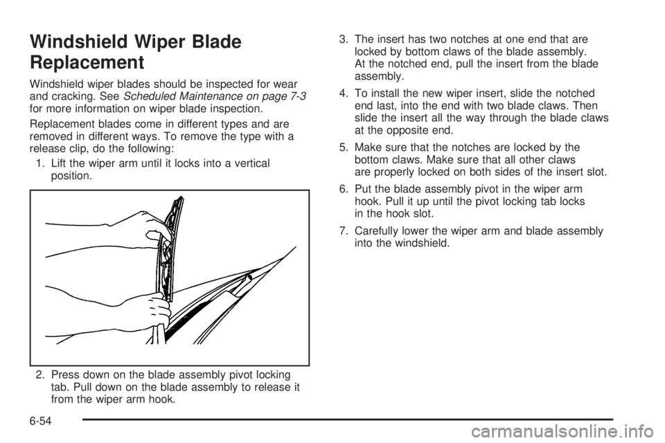
release clip, do the following:
1. Lift the wiper arm until it locks into a vertical
position.
2. Press down on the blade assembly pivot locking
tab. Pull down on the blade assembly to release it
from the wiper arm hook.3. The insert has two notches at one end that are
locked by bottom claws of the blade assembly.
At the notched end, pull the insert from the blade
assembly.
4. To install the new wiper insert, slide the notched
end last, into the end with two blade claws. Then
slide the insert all the way through the blade claws
at the opposite end.
5. Make sure that the notches are locked by the
bottom claws. Make sure that all other claws
are properly locked on both sides of the insert slot.
6. Put the blade assembly pivot in the wiper arm
hook. Pull it up until the pivot locking tab locks
in the hook slot.
7. Carefully lower the wiper arm and blade assembly
into the windshield.
6-54
Page 330 of 424

TPMS Sensor Matching Process
Each TPMS sensor has a unique identification code.
Any time you rotate your vehicle’s tires or replace one or
more of the TPMS sensors, the identification codes
will need to be matched to the new tire/wheel position.
The sensors are matched to the tire/wheel positions
in the following order: driver side front tire, passenger
side front tire, passenger side rear tire, and driver
side rear tire using a TPMS diagnostic tool. See your
dealer/retailer for service.
The TPMS sensors can also be matched to each
tire/wheel position by increasing or decreasing the tire’s
air pressure. If increasing the tire’s air pressure, do
not exceed the maximum inflation pressure indicated on
the tire’s sidewall.
To decrease air-pressure out of a tire you can use the
pointed end of the valve cap, a pencil-style air pressure
gage, or a key.
You have two minutes to match the first tire/wheel
position, and five minutes overall to match all four tire/
wheel positions. If it takes longer than two minutes,
to match the first tire and wheel, or more than
five minutes to match all four tire and wheel positions
the matching process stops and you need to start over.The TPMS sensor matching process is outlined below:
1. Set the parking brake.
2. Turn the ignition switch to ON/RUN with the
engine off.
3. Press the Remote Keyless Entry (RKE) transmitter’s
LOCK and UNLOCK buttons at the same time for
approximately five seconds. The horn sounds twice
to signal the receiver is in relearn mode and
TIRE LEARNING ACTIVE message displays on the
DIC screen.
If your vehicle does not have RKE, press the Driver
Information Center (DIC) vehicle information
button until the PRESS
VTO RELEARN TIRE
POSITIONS message displays. The horn sounds
twice to signal the receiver is in relearn mode
and TIRE LEARNING ACTIVE message displays on
the DIC screen.
If your vehicle does not have RKE or DIC buttons,
press the trip odometer reset stem located on
the instrument panel cluster until the PRESS
VTO
RELEARN TIRE POSITIONS message displays.
The horn sounds twice to signal the receiver
is in relearn mode and TIRE LEARNING ACTIVE
message displays on the DIC screen.
4. Start with the driver side front tire.
6-68
Page 331 of 424

5. Remove the valve cap from the valve cap stem.
Activate the TPMS sensor by increasing or
decreasing the tire’s air pressure for five seconds,
or until a horn chirp sounds. The horn chirp,
which may take up to 30 seconds to sound,
confirms that the sensor identification code has
been matched to this tire and wheel position.
6. Proceed to the passenger side front tire, and repeat
the procedure in Step 5.
7. Proceed to the passenger side rear tire, and repeat
the procedure in Step 5.
8. Proceed to the driver side rear tire, and repeat the
procedure in Step 5. The horn sounds two times to
indicate the sensor identification code has been
matched to the driver side rear tire, and that
the TPMS sensor matching process is no longer
active. The TIRE LEARNING ACTIVE message on
the DIC display screen goes off.
9. Turn the ignition switch to LOCK/OFF.
10. Set all four tires to the recommended air pressure
level as indicated on the Tire and Loading
Information label.
11. Put the valve caps back on the valve stems.Tire Inspection and Rotation
Inspect tires regularly for signs of wear or damage.
Also inspect the spare tire. For more information
on tire inspection, seeWhen It Is Time for
New Tires on page 6-72.
Tires should be rotated every 5,000 to 8,000 miles
(8 000 to 13 000 km). SeeScheduled Maintenance
on page 7-3.
The purpose of a regular tire rotation is to achieve
a uniform wear for all tires on the vehicle. This
will ensure that the vehicle continues to perform
most like it did when the tires were new. The
first rotation is the most important. SeeScheduled
Maintenance on page 7-3.
Any time you notice unusual wear, rotate the tires
as soon as possible and check wheel alignment.
Also check for damaged tires or wheels. See
When It Is Time for New Tires on page 6-72and
Wheel Replacement on page 6-76.
6-69
Page 336 of 424
Vehicles that have a tire pressure monitoring system
could give an inaccurate low-pressure warning if
non-TPC Spec rated tires are installed on your vehicle.
Non-TPC Spec rated tires may give a low-pressure
warning that is higher or lower than the proper warning
level you would get with TPC Spec rated tires. See
Tire Pressure Monitor System on page 6-65.
Your vehicle’s original equipment tires are listed on the
Tire and Loading Information label. SeeLoading the
Vehicle on page 5-17, for more information about
the Tire and Loading Information label and its location
on your vehicle.
Different Size Tires and Wheels
If you add wheels or tires that are a different size than
your original equipment wheels and tires, this could
affect the way your vehicle performs, including its
braking, ride and handling characteristics, stability, and
resistance to rollover. Additionally, if your vehicle
has electronic systems such as anti-lock brakes, rollover
airbags, traction control, and electronic stability control,
the performance of these systems can be affected.
{WARNING:
If you add different sized wheels, your vehicle may
not provide an acceptable level of performance
and safety if tires not recommended for those
wheels are selected. You may increase the
chance that you will crash and suffer serious
injury. Only use GM specific wheel and tire
systems developed for your vehicle, and have
them properly installed by a GM certified
technician.
SeeBuying New Tires on page 6-73andAccessories
and Modications on page 6-3for additional information.
6-74
Page 342 of 424
Changing a Flat Tire
If a tire goes flat, avoid further tire and wheel damage
by driving slowly to a level place. Turn on the hazard
warning flashers. SeeHazard Warning Flashers
on page 4-3.
{WARNING:
Changing a tire can be dangerous. The vehicle
can slip off the jack and roll over or fall on you or
other people. You and they could be badly injured
or even killed. Find a level place to change your
tire. To help prevent the vehicle from moving:
1. Set the parking brake firmly.
2. Put the shift lever in P (Park).
WARNING: (Continued)
WARNING: (Continued)
3. Turn off the engine and do not restart while
the vehicle is raised.
4. Do not allow passengers to remain in the
vehicle.
To be even more certain the vehicle will not move,
you should put blocks at the front and rear of the
tire farthest away from the one being changed.
That would be the tire, on the other side, at the
opposite end of the vehicle.
6-80
Page 343 of 424
When the vehicle has a flat tire (B), use the following
example as a guide to assist you in the placement
of wheel blocks (A).
A. Wheel Block
B. Flat Tire
The following information explains how to use the jack
and change a tire.Removing the Spare Tire and Tools
If you have a cargo van or a passenger van, the
equipment you will need is located in the passenger
side rear corner of the vehicle.
Remove the retaining wing bolt and lift it off of the
mounting bracket.
If you have a van with the 15-passenger seating
arrangement, the equipment you will need is secured on
the rear floor of the passenger side of the vehicle.
6-81