Page 309 of 407
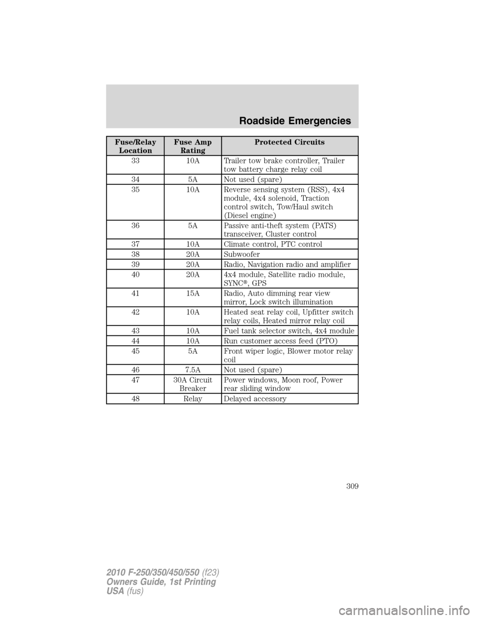
Fuse/Relay
LocationFuse Amp
RatingProtected Circuits
33 10A Trailer tow brake controller, Trailer
tow battery charge relay coil
34 5A Not used (spare)
35 10A Reverse sensing system (RSS), 4x4
module, 4x4 solenoid, Traction
control switch, Tow/Haul switch
(Diesel engine)
36 5A Passive anti-theft system (PATS)
transceiver, Cluster control
37 10A Climate control, PTC control
38 20A Subwoofer
39 20A Radio, Navigation radio and amplifier
40 20A 4x4 module, Satellite radio module,
SYNC�, GPS
41 15A Radio, Auto dimming rear view
mirror, Lock switch illumination
42 10A Heated seat relay coil, Upfitter switch
relay coils, Heated mirror relay coil
43 10A Fuel tank selector switch, 4x4 module
44 10A Run customer access feed (PTO)
45 5A Front wiper logic, Blower motor relay
coil
46 7.5A Not used (spare)
47 30A Circuit
BreakerPower windows, Moon roof, Power
rear sliding window
48 Relay Delayed accessory
Roadside Emergencies
309
2010 F-250/350/450/550(f23)
Owners Guide, 1st Printing
USA(fus)
Page 310 of 407
Power distribution box
The power distribution box is located in the engine compartment. The
power distribution box contains high-current fuses that protect your
vehicle’s main electrical systems from overloads.
WARNING:Always disconnect the battery before servicing high
current fuses.
WARNING:To reduce risk of electrical shock, always replace
the cover to the Power Distribution Box before reconnecting the
battery or refilling fluid reservoirs.
If the battery has been disconnected and reconnected, refer to the
Batterysection of theMaintenance and Specificationschapter.
The high-current fuses are coded as follows:
Fuse/Relay
LocationFuse Amp
RatingProtected Circuits
1 Relay Blower motor/Variable blower control
(Dual zone climate control)
2 Relay Electronic shift-on-the-fly (ESOF)
Lo-Hi
3 Relay Heater mirror
4 — Not used
5 30A* Trailer brake controller (TBC)
Roadside Emergencies
310
2010 F-250/350/450/550(f23)
Owners Guide, 1st Printing
USA(fus)
Page 311 of 407
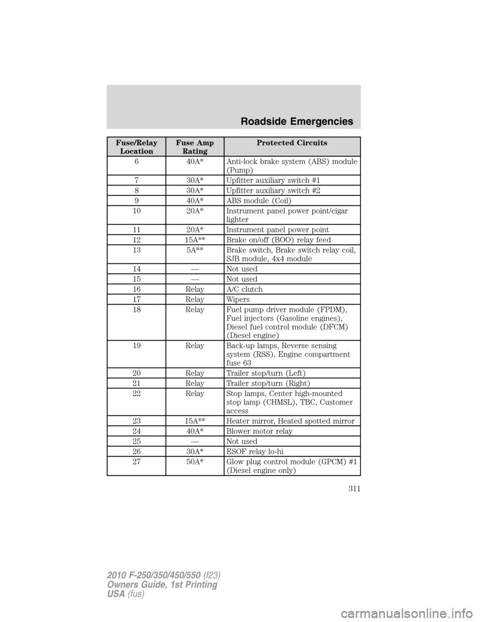
Fuse/Relay
LocationFuse Amp
RatingProtected Circuits
6 40A* Anti-lock brake system (ABS) module
(Pump)
7 30A* Upfitter auxiliary switch #1
8 30A* Upfitter auxiliary switch #2
9 40A* ABS module (Coil)
10 20A* Instrument panel power point/cigar
lighter
11 20A* Instrument panel power point
12 15A** Brake on/off (BOO) relay feed
13 5A** Brake switch, Brake switch relay coil,
SJB module, 4x4 module
14 — Not used
15 — Not used
16 Relay A/C clutch
17 Relay Wipers
18 Relay Fuel pump driver module (FPDM),
Fuel injectors (Gasoline engines),
Diesel fuel control module (DFCM)
(Diesel engine)
19 Relay Back-up lamps, Reverse sensing
system (RSS), Engine compartment
fuse 63
20 Relay Trailer stop/turn (Left)
21 Relay Trailer stop/turn (Right)
22 Relay Stop lamps, Center high-mounted
stop lamp (CHMSL), TBC, Customer
access
23 15A** Heater mirror, Heated spotted mirror
24 40A* Blower motor relay
25 — Not used
26 30A* ESOF relay lo-hi
27 50A* Glow plug control module (GPCM) #1
(Diesel engine only)
Roadside Emergencies
311
2010 F-250/350/450/550(f23)
Owners Guide, 1st Printing
USA(fus)
Page 312 of 407
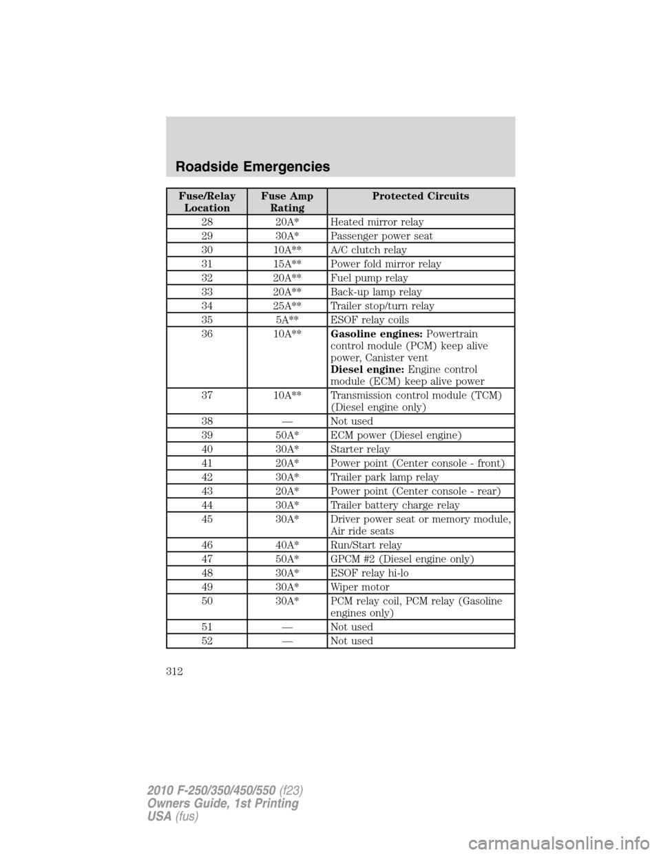
Fuse/Relay
LocationFuse Amp
RatingProtected Circuits
28 20A* Heated mirror relay
29 30A* Passenger power seat
30 10A** A/C clutch relay
31 15A** Power fold mirror relay
32 20A** Fuel pump relay
33 20A** Back-up lamp relay
34 25A** Trailer stop/turn relay
35 5A** ESOF relay coils
36 10A**Gasoline engines:Powertrain
control module (PCM) keep alive
power, Canister vent
Diesel engine:Engine control
module (ECM) keep alive power
37 10A** Transmission control module (TCM)
(Diesel engine only)
38 — Not used
39 50A* ECM power (Diesel engine)
40 30A* Starter relay
41 20A* Power point (Center console - front)
42 30A* Trailer park lamp relay
43 20A* Power point (Center console - rear)
44 30A* Trailer battery charge relay
45 30A* Driver power seat or memory module,
Air ride seats
46 40A* Run/Start relay
47 50A* GPCM #2 (Diesel engine only)
48 30A* ESOF relay hi-lo
49 30A* Wiper motor
50 30A* PCM relay coil, PCM relay (Gasoline
engines only)
51 — Not used
52 — Not used
Roadside Emergencies
312
2010 F-250/350/450/550(f23)
Owners Guide, 1st Printing
USA(fus)
Page 313 of 407
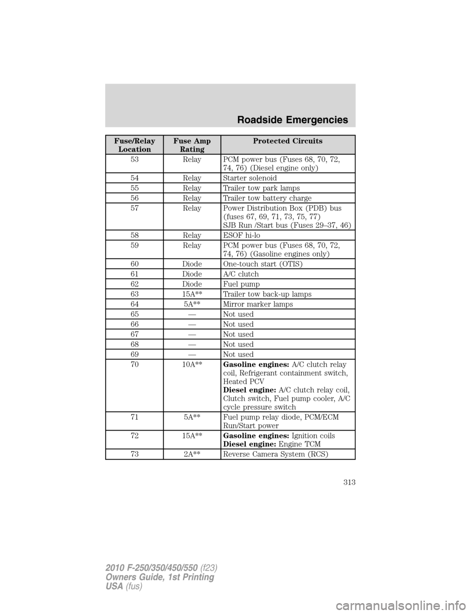
Fuse/Relay
LocationFuse Amp
RatingProtected Circuits
53 Relay PCM power bus (Fuses 68, 70, 72,
74, 76) (Diesel engine only)
54 Relay Starter solenoid
55 Relay Trailer tow park lamps
56 Relay Trailer tow battery charge
57 Relay Power Distribution Box (PDB) bus
(fuses 67, 69, 71, 73, 75, 77)
SJB Run /Start bus (Fuses 29–37, 46)
58 Relay ESOF hi-lo
59 Relay PCM power bus (Fuses 68, 70, 72,
74, 76) (Gasoline engines only)
60 Diode One-touch start (OTIS)
61 Diode A/C clutch
62 Diode Fuel pump
63 15A** Trailer tow back-up lamps
64 5A** Mirror marker lamps
65 — Not used
66 — Not used
67 — Not used
68 — Not used
69 — Not used
70 10A**Gasoline engines:A/C clutch relay
coil, Refrigerant containment switch,
Heated PCV
Diesel engine:A/C clutch relay coil,
Clutch switch, Fuel pump cooler, A/C
cycle pressure switch
71 5A** Fuel pump relay diode, PCM/ECM
Run/Start power
72 15A**Gasoline engines:Ignition coils
Diesel engine:Engine TCM
73 2A** Reverse Camera System (RCS)
Roadside Emergencies
313
2010 F-250/350/450/550(f23)
Owners Guide, 1st Printing
USA(fus)
Page 314 of 407
Fuse/Relay
LocationFuse Amp
RatingProtected Circuits
74 20A**Gasoline engines:Vehicle power
(VPWR): Heated exhaust gas oxygen
sensor, CMS, Mass air flow sensor,
Electronic vapor management valve,
CMCV, Variable cam timing, IMTV
Diesel engine:VPWR: Engine loads
75 5A** Back-up relay coil power
76 20A**Gasoline engines:VPWR: PCM
Diesel engine:VPWR: ECM
77 10A** ABS module logic
* Cartridge fuses ** Mini fuses
CHANGING A FLAT TIRE
If you get a flat tire while driving:
•do not brake heavily.
•gradually decrease the vehicle’s speed.
•hold the steering wheel firmly.
•slowly move to a safe place on the side of the road.
Your vehicle may be equipped with a conventional spare tire that is
different in one or more of the following: type, brand, size, speed rating
and tread design. If this is the case, this dissimilar spare tire is still rated
for your vehicle loads (GAWR and GVWR).Temporary spare tires are not
equipped with Tire Pressure Monitor System (TPMS) sensors if the
system is present.
WARNING:The use of tire sealant may damage your Tire
Pressure Monitoring System (if equipped) and should not be
used.
WARNING:If your vehicle is equipped with a Tire Pressure
Monitoring System, refer toTire Pressure Monitoring System
(TPMS)in theTires, Wheels and Loadingchapter for more
information. If the tire pressure monitor sensor becomes damaged, it
will no longer function.
Roadside Emergencies
314
2010 F-250/350/450/550(f23)
Owners Guide, 1st Printing
USA(fus)
Page 317 of 407
Stopping and securing the vehicle
WARNING:To help prevent the vehicle from moving when you
change a tire, be sure the parking brake is set, then block (in
both directions) the wheel that is diagonally opposite to the tire being
changed.
Refer to the instruction sheet (located in the glove box) for detailed tire
change instructions.
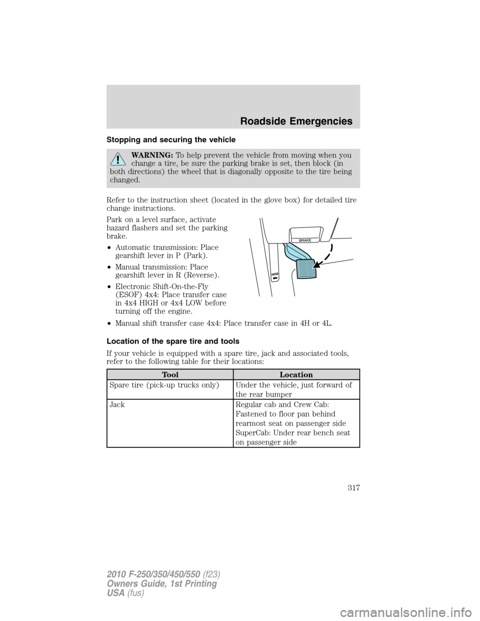
Park on a level surface, activate
hazard flashers and set the parking
brake.
•Automatic transmission: Place
gearshift lever in P (Park).
•Manual transmission: Place
gearshift lever in R (Reverse).
•Electronic Shift-On-the-Fly
(ESOF) 4x4: Place transfer case
in 4x4 HIGH or 4x4 LOW before
turning off the engine.
•Manual shift transfer case 4x4: Place transfer case in 4H or 4L.
Location of the spare tire and tools
If your vehicle is equipped with a spare tire, jack and associated tools,
refer to the following table for their locations:
Tool Location
Spare tire (pick-up trucks only) Under the vehicle, just forward of
the rear bumper
Jack Regular cab and Crew Cab:
Fastened to floor pan behind
rearmost seat on passenger side
SuperCab: Under rear bench seat
on passenger side
Roadside Emergencies
317
2010 F-250/350/450/550(f23)
Owners Guide, 1st Printing
USA(fus)
Page 318 of 407
![FORD SUPER DUTY 2010 2.G Owners Manual Tool Location
Jack handle, lug wrench, lug
wrench extension (only available
on Dual Rear Wheel [DRW]
vehicles) and wheel chock (only
available on Single Rear Wheel
[SRW] vehicles equipped with a
diese FORD SUPER DUTY 2010 2.G Owners Manual Tool Location
Jack handle, lug wrench, lug
wrench extension (only available
on Dual Rear Wheel [DRW]
vehicles) and wheel chock (only
available on Single Rear Wheel
[SRW] vehicles equipped with a
diese](/manual-img/11/5288/w960_5288-317.png)
Tool Location
Jack handle, lug wrench, lug
wrench extension (only available
on Dual Rear Wheel [DRW]
vehicles) and wheel chock (only
available on Single Rear Wheel
[SRW] vehicles equipped with a
diesel engine)Regular cab: Fastened to floor
behind driver seat
SuperCab: Fastened to floor under
rear seat
Crew Cab: Fastened to floor
behind rear seat at driver side
Key and spare tire lock In the glove box
Jack instruction sheet Under the jack tool kit
Removing the spare tire (with spare tire carrier only)
1. The following tools are required to remove the spare tire:
•one handle extension and two
typical extensions. To assemble,
align button with hole and slide
parts together. To disconnect,
depress button and pull apart.
•one wheel nut wrench. Slide over
square end of jack handle.
•Vehicles equipped with dual
rear wheels,insert the lug
wrench extension into the lug
wrench to reach the lug nuts.
Roadside Emergencies
318
2010 F-250/350/450/550(f23)
Owners Guide, 1st Printing
USA(fus)