Page 28 of 274
GAUGES
Some of the gauges shown are optional based on vehicle equipment; your
vehicle may not have some of the gauges shown in this section.
Speedometer:Indicates the
current vehicle speed.
Tachometer:Indicates the engine
speed in revolutions per minute.
Driving with your tachometer
pointer continuously at the top of
the scale may damage the engine.
Odometer:Registers the total miles
(kilometers) of the vehicle.
Instrument Cluster
28
2010 F-650/750(f67)
Supplement(supplement), 1st Printing
USA(fus)
Page 29 of 274

Trip odometer:Registers the miles
(kilometers) of individual journeys.
To reset, press the control.
Fuel gauge:Indicates
approximately how much fuel is left
in the fuel tank (when the ignition
is in the on position). If your vehicle
is equipped with dual fuel tanks, the
engine will draw fuel from the
driver-side fuel tank only. With dual
fuel tanks, the vehicle will be
equipped with a fuel transfer pump system that will draw fuel from the
passenger-side fuel tank and send fuel to the driver-side fuel tank. The
driver-side fuel tank must have fuel in it at all times otherwise the
vehicle may stall and may be difficult to re-start. The fuel gauge reads
the fuel level only from the driver-side fuel tank.
Engine coolant temperature
gauge:Indicates engine coolant
temperature. At normal operating
temperature, the needle will be in
the normal range (as indicated by
the arrows).If it enters the red
section, the engine is
overheating. Stop the vehicle as
soon as safely possible, switch
off the engine and let the engine
cool.
WARNING:Never remove the coolant reservoir cap while the
engine is running or hot. The contents may be under pressure,
and could cause burns or other serious injury.
H
C
Instrument Cluster
29
2010 F-650/750(f67)
Supplement(supplement), 1st Printing
USA(fus)
Page 30 of 274

Engine oil pressure gauge:
Indicates engine oil pressure. The needle should stay in the normal
operating range (as indicated by the arrows). If the needle falls below
the normal range, stop the vehicle, turn off the engine and check the
engine oil level. Add oil if needed. If the oil level is correct, have your
vehicle checked at your dealership or by a qualified technician.
Battery voltage gauge:Indicates
the battery voltage when the
ignition is in the on position. If the
pointer moves and stays outside the
normal operating range (as
indicated by the arrows), have the
vehicle’s electrical system checked
as soon as possible.
Transmission fluid temperature
gauge (if equipped, automatic
transmission only):
Indicates the temperature of the
transmission fluid. The normal
temperature range is 150°–230°F
(65°–110°C). Readings of
230°–250°F (110°–121°C) are
satisfactory for intermittent
operation and are not cause for
alarm. Operation above 250°F
(121°C) can cause the fluid to break down and will result in component
damage.
818
Instrument Cluster
30
2010 F-650/750(f67)
Supplement(supplement), 1st Printing
USA(fus)
Page 31 of 274
Hourmeter (if equipped):
Registers the hours the engine has
been operating.
UltraShift gear display (if
equipped):Refer to theUltraShift
Driver Instructions Manualfor the
function of this display.
Air filter restriction gauge:
Measures the vacuum inside the air
cleaner. The more the air cleaner is
restricted (dirty, clogged), the
higher the vacuum reading. Change
the air filter when the gauge reads
25 inches. After installation of the
new filter element, reset the gauge
to 0.
Instrument Cluster
31
2010 F-650/750(f67)
Supplement(supplement), 1st Printing
USA(fus)
Page 32 of 274

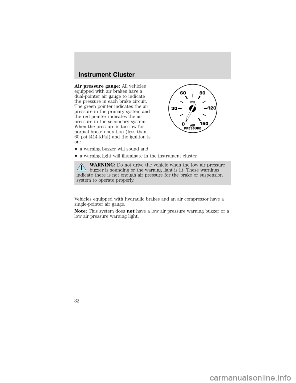
Air pressure gauge:All vehicles
equipped with air brakes have a
dual-pointer air gauge to indicate
the pressure in each brake circuit.
The green pointer indicates the air
pressure in the primary system and
the red pointer indicates the air
pressure in the secondary system.
When the pressure is too low for
normal brake operation (less than
60 psi [414 kPa]) and the ignition is
on:
•a warning buzzer will sound and
•a warning light will illuminate in the instrument cluster
WARNING:Do not drive the vehicle when the low air pressure
buzzer is sounding or the warning light is lit. These warnings
indicate there is not enough air pressure for the brake or suspension
system to operate properly.
Vehicles equipped with hydraulic brakes and an air compressor have a
single-pointer air gauge.
Note:This system doesnothave a low air pressure warning buzzer or a
low air pressure warning light.
0 30120 90 60
150AIR
PRESSURE
PSI
Instrument Cluster
32
2010 F-650/750(f67)
Supplement(supplement), 1st Printing
USA(fus)
Page 74 of 274

Safety belt extension assembly
If the safety belt is too short when fully extended, there is an eight inch
(20 cm) safety belt extension assembly that can be added (part number
611C22). This assembly can be obtained from your dealer at no cost.
Use only extensions manufactured by the same supplier as the safety
belt. Manufacturer identification is located at the end of the webbing on
the label. Also, use the safety belt extension only if the safety belt is too
short for you when fully extended.
WARNING:Do not use extensions to change the fit of the
shoulder belt across the torso.
Safety belt maintenance
Inspect the safety belt systems periodically to make sure they work
properly and are not damaged. Inspect the safety belts to make sure
there are no nicks, tears or cuts. Replace if necessary. All safety belt
assemblies, including retractors, buckles, front seat belt buckle
assemblies, buckle support assemblies (slide bar-if equipped), shoulder
belt height adjusters (if equipped), shoulder belt guide on seatback (if
equipped), child safety seat tether anchors, and attaching hardware,
should be inspected after a collision.
WARNING:Ford Motor Company recommends that all safety
belt assemblies used in vehicles involved in a collision be
inspected for proper function and replaced, if necessary. Safety belt
assemblies not in use during a collision should also be inspected and
replaced if either damage or improper operation is noted.
WARNING:Failure to inspect and if necessary replace the
safety belt assembly under the above conditions could result in
severe personal injuries in the event of a collision.
Refer toInteriorin theCleaningchapter.
Safety belt warning light and indicator chime
The safety belt warning light illuminates in the instrument cluster and a
chime sounds to remind the occupants to fasten their safety belts.
Seating and Safety Restraints
74
2010 F-650/750(f67)
Supplement(supplement), 1st Printing
USA(fus)
Page 75 of 274

Conditions of operation
If... Then...
The driver’s safety belt is not
buckled before the ignition
switch has been turned to on...The safety belt warning light
illuminates 1-2 minutes and the
warning chime sounds 4-8 seconds.
The driver’s safety belt is
buckled while the indicator
light is illuminated and the
warning chime is sounding...The safety belt warning light and
warning chime turn off.
The driver’s safety belt is
buckled before the ignition
switch has been turned to on...The safety belt warning light and
indicator chime remain off.
Belt-Minder�
The Belt-Minder�feature is a supplemental warning to the safety belt
warning function. This feature provides additional reminders to the
driver that the driver’s safety belt is unbuckled by intermittently
sounding a chime and illuminating the safety belt warning lamp in the
instrument cluster.
If... Then...
The driver’s safety belt is not
buckled before the vehicle has
reached at least 3 mph
(5 km/h) and 1-2 minutes have
elapsed since the ignition
switch has been turned to on...The Belt-Minder�feature is activated
- the safety belt warning light
illuminates and the warning chime
sounds for six seconds every
30 seconds, repeating for
approximately five minutes or until
safety belt is buckled.
The driver’s safety belt is
buckled while the safety belt
indicator light is illuminated
and the safety belt warning
chime is sounding...The Belt-Minder�feature will not
activate.
The driver’s safety belt is
buckled before the ignition
switch is turned to the on
position...The Belt-Minder�feature will not
activate.
Seating and Safety Restraints
75
2010 F-650/750(f67)
Supplement(supplement), 1st Printing
USA(fus)
Page 92 of 274

Note:When starting the engine, do not press the accelerator as engine
damage may result.
1. Ensure headlamps and all accessories are turned off, the parking
brake is applied and the transmission is in the neutral position (or P
[Park] for Allison 2200 transmissions).
2. Turn the key to the on position, but do not start the engine.
In cooler weather, the air intake
heater may activate the WAIT TO
START light in the instrument
cluster. If the WAIT TO START light
illuminates,do notcrank the engine
until the light goes off.
WARNING:If equipped with an air intake heater, DO NOT use
ether or any other starting fluids. The use of starting fluids
(ether) in an engine equipped with an air intake heater could cause an
explosion and result in property damage and/or personal injury.
3. When the WAIT TO START light turns off, turn the key to the start
position; when the engine starts, release the key.
If the engine does not start after 30 seconds of cranking, allow two
minutes for the starter to cool before trying again. Excessive cranking
may damage the starter.
After the engine starts:
•On some engines, the WAIT TO
START light should illuminate
after the engine starts. Allow the
engine to idle about three
minutes or until the engine
coolant temperature gauge begins to rise. Maintain idle speed until the
WAIT TO START light cycles off to indicate the air intake heater has
shut off (approximately six minutes). Operating the engine at higher
speeds will reduce the effectiveness of the air inlet heater.
WAIT
TO
START
WAIT
TO
START
Driving
92
2010 F-650/750(f67)
Supplement(supplement), 1st Printing
USA(fus)