Page 89 of 210
 88
SAFETY
DEVICES
CORRECT USE
OF THE
VEHICLE
WARNING
LIGHTS AND
MESSAGES
IN AN
EMERGENCY
VEHICLE
MAINTENANCE
TECHNICAL
SPECIFICATIONS
INDEX
DASHBOARD
AND CONTROLS SICUREZZA
AVVIAMENTO
E GUIDA
SPIE
E")
88
SAFETY
DEVICES
CORRECT USE
OF THE
VEHICLE
WARNING
LIGHTS AND
MESSAGES
IN AN
EMERGENCY
VEHICLE
MAINTENANCE
TECHNICAL
SPECIFICATIONS
INDEX
DASHBOARD
AND CONTROLS SICUREZZA
AVVIAMENTO
E GUIDA
SPIE
E MESSAGGI
IN EMERGENZA
MANUTENZIONE
E CURA
DATI TECNICI
INDICE
ALFABETICO
PARKING SENSORS
(where provided)
Parking sensors are located in the rear
bumper fig. 114and their function is to
inform the driver, through an intermittent
buzzer, about the presence of obstacles
behind the vehicle.
In order to deactivate the parking sensors,
press button A-fig. 115present between
the commands on the bridge of the cen-
tral compartment. The deactivation is sig-
nalled by the lighting of the led Bon the
button.
In order to re-activate them, press button
Aagain.
When the distance from the obstacle sit-
uated behind the vehicle diminishes, it cor-
responds with an increase in the frequen-
cy of the beeping.
WARNING The condition of the parking
sensors (activated or deactivated) is mem-
orised upon switching off the engine.BUZZER WARNINGS
When the reverse gear is engaged an in-
termittent acoustic signal is automatically
activated.
The acoustic signal:
❒becomes louder as the distance be-
tween the vehicle and the obstacle de-
creases;
❒becomes continuous when the distance
between the vehicle and the obstacle is
less than 30 cm and stops immediately
if the distance raises;
❒is constant if the distance is unvaried;
if this situation concerns the side sen-
sors, the buzzer will stop after about
3 seconds to avoid, for example, warn-
ing indications in the event of manoeu-
vres along walls.FAILURE INDICATIONS
Parking sensor failures, if any, will be in-
dicated when engaging reverse by the
buzzer and the turning on of led
B-fig. 115together with the message on
the display.
fig. 114F0P0605mfig. 115F0P0106m
Page 90 of 210
 89
SAFETY
DEVICES
CORRECT USE
OF THE
VEHICLE
WARNING
LIGHTS AND
MESSAGES
IN AN
EMERGENCY
VEHICLE
MAINTENANCE
TECHNICAL
SPECIFICATIONS
INDEX
DASHBOARD
AND CONTROLS
GENERAL WARNINGS
❒When parking, ta")
89
SAFETY
DEVICES
CORRECT USE
OF THE
VEHICLE
WARNING
LIGHTS AND
MESSAGES
IN AN
EMERGENCY
VEHICLE
MAINTENANCE
TECHNICAL
SPECIFICATIONS
INDEX
DASHBOARD
AND CONTROLS
GENERAL WARNINGS
❒When parking, take the utmost care to
obstacles that may be set above or un-
der the sensors.
❒Objects set close to the vehicle, under
certain circumstances are not detected
and could therefore cause damages to
the vehicle or be damaged.
❒Indications sent by the sensors can be
altered by dirt, snow or ice deposited
on the sensors or by ultrasound sys-
tems (e.g.: truck pneumatic brakes or
pneumatic hammers) set nearby the ve-
hicle. For proper operation, the
parking sensors shall always
be clean from mud, dirt, snow
or ice. When cleaning the sen-
sors, take the utmost care to prevent
their damaging; do not use therefore
dry or rough clothes. Sensors shall be
washed with clean water and vehicle
detergent, if required.
Parking manoeuvres howev-
er are always under the dri-
ver’s responsibility that shall always
check the absence of people (spe-
cially children) or animals in the ma-
noeuvre space. This system is just a
help for the driver but she/he shall
never reduce attention during dan-
gerous manoeuvres even if performed
at low speed.
WARNING
OPERATION WITH
TRAILER
Deactivate parking sensors if you use the
vehicle with trailer.SOUND SYSTEM
(where provided)
For the operation of the radio with
CD/MP3 CD player (where provided),
read the instructions for use given in the
Supplement attached to this Owner Hand-
book.
SOUND SYSTEM PRESETTING
(where provided)
For details about the radio installed on the
vehicle and the relevant system, read the
instructions for use given in Supplement
“Sound System” attached to this Owner
Handbook.
For connection to existing
vehicle presetting system,
contact Fiat Dealership to prevent
any trouble that could impair vehicle
safety.
WARNING
Page 91 of 210
 90
SAFETY
DEVICES
CORRECT USE
OF THE
VEHICLE
WARNING
LIGHTS AND
MESSAGES
IN AN
EMERGENCY
VEHICLE
MAINTENANCE
TECHNICAL
SPECIFICATIONS
INDEX
DASHBOARD
AND CONTROLS
RADIO TRANSMITTERS
AND CELLULAR TELE")
90
SAFETY
DEVICES
CORRECT USE
OF THE
VEHICLE
WARNING
LIGHTS AND
MESSAGES
IN AN
EMERGENCY
VEHICLE
MAINTENANCE
TECHNICAL
SPECIFICATIONS
INDEX
DASHBOARD
AND CONTROLS
RADIO TRANSMITTERS
AND CELLULAR TELEPHONES
Radio transceiver equipment (e.g.: e-tacs
mobile phones, HAM radio systems and
the like) shall not be used inside the ve-
hicle unless a separate aerial is mounted
on the roof.
IMPORTANT The use of similar devices
inside the passenger compartment (with-
out separated aerial) produces radio-fre-
quency electromagnetic fields which, am-
plified by the resonance effects inside the
passenger compartment, may cause elec-
trical systems equipping the vehicle to mal-
function. This could compromise safety in
addition to constituting a potential hazard
for the passengers.
In addition, transmission and reception of
these devices may be affected by the
shielding effect of the vehicle body.
As concerns EC-approved mobile phones
(GSM, GPRS, UMTS), strictly comply with
the instructions for use provided by the
mobile phone’s manufacturer.ACCESSORIES
PURCHASED BY THE
OWNER
If after buying the vehicle, you decide to
install electrical accessories that require a
permanent electric supply (alarm, satellite
antitheft system, etc.) or accessories that
in any case burden the electric supply,
contact Fiat Dealership, whose qualified
personnel, besides suggesting the most
suitable devices belonging to Lineaccessori
Fiat, will also evaluate the overall electric
absorption, checking whether the vehicle
electric system is able to withstand the
load required, or whether it needs to be
integrated with a more powerful battery.
SICUREZZA
AVVIAMENTO
E GUIDA
SPIE
E MESSAGGI
IN EMERGENZA
MANUTENZIONE
E CURA
DATI TECNICI
INDICE
ALFABETICO
SICUREZZA
AVVIAMENTO
E GUIDA
SPIE
E MESSAGGI
IN EMERGENZA
MANUTENZIONE
E CURA
DATI TECNICI
INDICE
ALFABETICO
INSTALLATION OF
ELECTRIC/ELECTRONIC
DEVICES
Electric/electronic devices installed after
buying the vehicle and in after-market shall
bear the following marking:
Fiat Auto S.p.A. authorizes the installation
of transceivers, provided that installation
is workmanlike performed in compliance
with Manufacturer’s specifications at a spe-
cialised service centre.
IMPORTANT The installation of devices
involving modifications of vehicle charac-
teristics may determine the withdrawal of
the driving licence by the appointed pub-
lic authorities and the forfeiture of the
warranty as concerns defects/failures due
to said modification or leading directly or
indirectly to it.
Fiat Auto S.p.A. declines all responsibility
due to damages connected with the in-
stallation of accessories/devices not sup-
plied by or recommended by Fiat Auto
S.p.A. and installed not in compliance with
the specified prescriptions.
Page 92 of 210
 91
SAFETY
DEVICES
CORRECT USE
OF THE
VEHICLE
WARNING
LIGHTS AND
MESSAGES
IN AN
EMERGENCY
VEHICLE
MAINTENANCE
TECHNICAL
SPECIFICATIONS
INDEX
DASHBOARD
AND CONTROLS
Refuelling
To guarantee full tank fi")
91
SAFETY
DEVICES
CORRECT USE
OF THE
VEHICLE
WARNING
LIGHTS AND
MESSAGES
IN AN
EMERGENCY
VEHICLE
MAINTENANCE
TECHNICAL
SPECIFICATIONS
INDEX
DASHBOARD
AND CONTROLS
Refuelling
To guarantee full tank filling, carry out two
refuelling operations after the first click of
the fuel delivery gun. Avoid further top-
ping up operations that could cause dam-
ages to the fuel system.
FUEL FILLER CAP fig. 116
To carry out fuelling, open lid A, fit the ig-
nition key into the cap lock and turn it
counterclockwise, then loosen cap B.
The sealing of the tank may cause light
pressurising in the tank. A little breathing
off, while slackening the cap, is absolutely
normal.
When refuelling, secure the cap to the de-
vice Cinside the lid.
fig. 116F0F0107m
AT THE FILLING
STATION
Operation at cold temperatures
If the outside temperature is very low, the
diesel thickens due to the formation of
paraffins and could clog the diesel fuel fil-
ter.
In order to avoid these problems, differ-
ent types of diesel are distributed ac-
cording to the season: summer type, win-
ter type and arctic type (cold, mountain
areas). If refuelling with diesel fuel not suit-
able for the current temperature, mix
diesel fuel with TUTELA DIESEL ART ad-
ditive in the proportions stated on the can,
putting first the antifreeze in the tank and
then the diesel fuel.
Refuel with local diesel fuel if the vehicle
is used/parked in the mountains or in cold
areas for a long period.
In this event you are recommended to
keep an amount of fuel higher than 50% in
the tank.The vehicle must only be filled
with diesel fuel for motor ve-
hicles, in compliance with Eu-
ropean Standard EN590. The
use of other products or mixtures may
irreparably damage the engine with in-
validation of the warranty due to the
damage caused. In the event of acci-
dentally filling with another type of fu-
el, do not start the engine and empty
the tank. If the engine has been run
even for only a very short time, in ad-
dition to the tank, it is also necessary
to drain out the whole fuel circuit.
Keep naked flames or light-
ed cigarettes away from the
fuel filler hole as there is a danger of
fire. Do not bend too close to the hole
either so as not to breathe in harmful
vapours.
WARNING
During refuelling, do not open
the left sliding door due to the
fact that the open fuel door.
Page 93 of 210
 92
SAFETY
DEVICES
CORRECT USE
OF THE
VEHICLE
WARNING
LIGHTS AND
MESSAGES
IN AN
EMERGENCY
VEHICLE
MAINTENANCE
TECHNICAL
SPECIFICATIONS
INDEX
DASHBOARD
AND CONTROLS
DIESEL PARTICULATE FILTER
(DPF) (whe")
92
SAFETY
DEVICES
CORRECT USE
OF THE
VEHICLE
WARNING
LIGHTS AND
MESSAGES
IN AN
EMERGENCY
VEHICLE
MAINTENANCE
TECHNICAL
SPECIFICATIONS
INDEX
DASHBOARD
AND CONTROLS
DIESEL PARTICULATE FILTER
(DPF) (where provided)
The Diesel Particulate Filter is a mechan-
ical filter, integral with the exhaust system,
that physically traps particulates present
in the exhaust gases of Diesel engine.
The diesel particulate filter has been
adopted to eliminate almost totally par-
ticulates in compliance with current / fu-
ture law regulations.
During normal use of the vehicle, the en-
gine control unit records a set of data (e.g.:
travel time, type of route, temperatures,
etc.) and it will then calculate how much
particulates has been trapped by the filter.
Since this filter physically traps particulates,
it shall be cleaned (reclaimed) at regular
intervals by burning carbon particles.
Reclaiming procedure is controlled auto-
matically by the engine control unit ac-
cording to the filter conditions and the
conditions of use of the vehicle.
During reclaiming the following phenom-
ena could take place: idling slight increase,
fan activation, slight smoke increase, high
exhaust temperatures. These situations
shall not be considered as faults and they
do not affect vehicle performance and en-
vironment.
During normal service the
diesel particulate filter (DPF)
reaches high temperatures. Do not
therefore park the vehicle over in-
flammable materials (grass, dry leaves,
pine needles, etc.): fire hazard.
WARNING
During normal service the
catalyst reaches high tem-
peratures. Do not therefore park the
vehicle over inflammable materials
(grass, dry leaves, pine needles, etc.):
fire hazard.
WARNING
PROTECTING THE
ENVIRONMENT
The devices for curtailing diesel engine
emissions are:
❒oxidising catalytic converter;
❒ exhaust gas recirculation system
(E.G.R.);
❒diesel particulate filter (DPF) (where
provided).
Diesel re-ignition pump
In case of the lack of fuel, it is necessary
to re-start the circuit:
❒ fill the fuel tank with at least 5 litres of
diesel;
❒ activate the manual re-operation pump,
situated under the engine casing under
the protection, until the fuel appears in
the transparent tube;
❒ activate the starting engine, until the en-
gine starts.
fig. 117F0F0357m
Page 94 of 210
93
CORRECT USE
OF THE
VEHICLE
WARNING
LIGHTS AND
MESSAGES
IN AN
EMERGENCY
VEHICLE
MAINTENANCE
TECHNICAL
SPECIFICATIONS
INDEX
DASHBOARD
AND CONTROLS
SAFETY
DEVICES
SEAT BELTS .......................................................................... 94
S.B.R. SYSTEM ...................................................................... 96
PRETENSIONERS ................................................................ 96
CARRYING CHILDREN SAFELY .................................... 99
PRESETTING FOR MOUNTING THE
“UNIVERSAL ISOFIX” CHILD RESTRAINT
SYSTEM .................................................................................. 105
FRONT AIR BAGS .............................................................. 106
SIDE AIR BAGS .................................................................... 109
S S
A A
F F
E E
T T
Y Y
D D
E E
V V
I I
C C
E E
S S
Page 95 of 210
 94
CORRECT USE
OF THE
VEHICLE
WARNING
LIGHTS AND
MESSAGES
IN AN
EMERGENCY
VEHICLE
MAINTENANCE
TECHNICAL
SPECIFICATIONS
IINDEX
DASHBOARD
AND CONTROLS
SAFETY
DEVICES
SEAT BELTS
USING THE SEAT BELTS fig")
94
CORRECT USE
OF THE
VEHICLE
WARNING
LIGHTS AND
MESSAGES
IN AN
EMERGENCY
VEHICLE
MAINTENANCE
TECHNICAL
SPECIFICATIONS
IINDEX
DASHBOARD
AND CONTROLS
SAFETY
DEVICES
SEAT BELTS
USING THE SEAT BELTS fig. 1
The belt should be worn keeping the chest
straight and rested against the seat back.
To fasten the seat belts, take hold the
tongue Aand insert it into the buckle B,
until hearing the locking click.
At removal, if it jams, let it rewind for a
short stretch, then pull it out again with-
out jerking.
To unfasten the seat belts, press button
C. Guide the seat belt with your hand
while it is rewinding, to prevent it from
twisting.
The seat belt reel mechanism ensures that
the belt automatically adjusts to the wear-
er allowing him or her to move in com-
plete freedom.
When the vehicle is parked on a steep
slope the reel mechanism may block; this
is normal. The reel mechanism also pre-
vents the webbing coming out when it is
jerked or if the vehicle brakes sharply, is
in a collision or when cornering at high
speed.
The rear seat is fitted with inertial seat
belts with three anchor points and reel.
fig. 1F0P0108m
fig. 2F0P0111m
fig. 3F0P0112m
Never press button C-fig. 1
when travelling.
WARNING
Remember that in the event
of a violent collision, back
seat passengers not wearing seat belts
also represent a serious danger for
the front seat passengers.
WARNING
Make sure the backrest is
properly secured at both
sides to prevent it moves forward in
the event of sharp braking causing in-
juries to passengers.
WARNING
Page 96 of 210
 95
CORRECT USE
OF THE
VEHICLE
WARNING
LIGHTS AND
MESSAGES
IN AN
EMERGENCY
VEHICLE
MAINTENANCE
TECHNICAL
SPECIFICATIONS
INDEX
DASHBOARD
AND CONTROLS
SAFETY
DEVICES
ADJUSTING THE SEAT BELT
HEIGHT fig.")
95
CORRECT USE
OF THE
VEHICLE
WARNING
LIGHTS AND
MESSAGES
IN AN
EMERGENCY
VEHICLE
MAINTENANCE
TECHNICAL
SPECIFICATIONS
INDEX
DASHBOARD
AND CONTROLS
SAFETY
DEVICES
ADJUSTING THE SEAT BELT
HEIGHT fig. 4Always adjust the height of the seat belt
to fit the person wearing it. This could
greatly reduce the risk of injury in the case
of collision. The belt is adjusted properly
when the webbing passes approximately
halfway between the edge of the shoulder
and the neck.
The belt is adjusted properly when the
webbing passes approximately halfway be-
tween the edge of the shoulder and the
neck.
To adjust, press the grip Aand raise or
lower the slider.
Only adjust seat belt height
when the vehicle is station-
ary.
WARNINGAfter you have made the ad-
justment, always make sure
that the slider is locked firmly in one
of the preset positions. To do this,
with the grip released, exert a further
pressure to allow the anchoring de-
vice to catch if release did not take
place at one of the preset positions.
WARNING
fig. 4F0P0109mfig. 5F0P0110m
USING THE CENTRAL SEAT
BELT (where provided)
The central seat belt with three anchor
points can be fitted with reel A-fig. 5.
Remember that in the event
of a violent collision, back
seat passengers not wearing seat belts
also represent a serious danger for
the front seat passengers.
WARNING
 1
1 2
2 3
3 4
4 5
5 6
6 7
7 8
8 9
9 10
10 11
11 12
12 13
13 14
14 15
15 16
16 17
17 18
18 19
19 20
20 21
21 22
22 23
23 24
24 25
25 26
26 27
27 28
28 29
29 30
30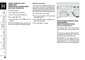 31
31 32
32 33
33 34
34 35
35 36
36 37
37 38
38 39
39 40
40 41
41 42
42 43
43 44
44 45
45 46
46 47
47 48
48 49
49 50
50 51
51 52
52 53
53 54
54 55
55 56
56 57
57 58
58 59
59 60
60 61
61 62
62 63
63 64
64 65
65 66
66 67
67 68
68 69
69 70
70 71
71 72
72 73
73 74
74 75
75 76
76 77
77 78
78 79
79 80
80 81
81 82
82 83
83 84
84 85
85 86
86 87
87 88
88 89
89 90
90 91
91 92
92 93
93 94
94 95
95 96
96 97
97 98
98 99
99 100
100 101
101 102
102 103
103 104
104 105
105 106
106 107
107 108
108 109
109 110
110 111
111 112
112 113
113 114
114 115
115 116
116 117
117 118
118 119
119 120
120 121
121 122
122 123
123 124
124 125
125 126
126 127
127 128
128 129
129 130
130 131
131 132
132 133
133 134
134 135
135 136
136 137
137 138
138 139
139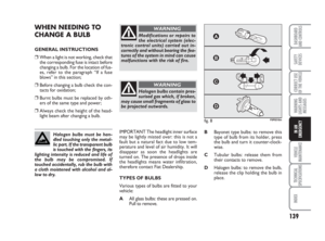 140
140 141
141 142
142 143
143 144
144 145
145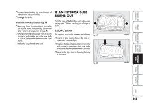 146
146 147
147 148
148 149
149 150
150 151
151 152
152 153
153 154
154 155
155 156
156 157
157 158
158 159
159 160
160 161
161 162
162 163
163 164
164 165
165 166
166 167
167 168
168 169
169 170
170 171
171 172
172 173
173 174
174 175
175 176
176 177
177 178
178 179
179 180
180 181
181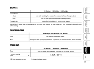 182
182 183
183 184
184 185
185 186
186 187
187 188
188 189
189 190
190 191
191 192
192 193
193 194
194 195
195 196
196 197
197 198
198 199
199 200
200 201
201 202
202 203
203 204
204 205
205 206
206 207
207 208
208 209
209 93
CORRECT USE
OF THE
VEHICLE
WARNING
LIGHTS AND
MESSAGES
IN AN
EMERGENCY
VEHICLE
MAINTENANCE
TECHNICAL
SPECIFICATIONS
INDEX
DASHBOARD
AND CONTROLS
SAFETY
DEVICES
SEAT BELTS ........................")