Page 71 of 315

WARNING! (Continued)
•Always make sure that objects cannot fall into the
driver foot well while the vehicle is moving.
Objects can become trapped under the brake pedal
and accelerator pedal causing a loss of vehicle
control.
•If required, mounting posts must be properly
installed, if not equipped from the factory.
Failure to properly follow floor mat installation or
mounting can cause interference with the brake
pedal and accelerator pedal operation causing loss
of control of the vehicle.
Periodic Safety Checks You Should Make Outside
the Vehicle
Tires
Examine tires for excessive tread wear and uneven wear
patterns. Check for stones, nails, glass, or other objectslodged in the tread. Inspect the tread and sidewall for
cuts and cracks. Check the wheel nuts for tightness.
Check the tires (including spare) for proper pressure.
Lights
Have someone observe the operation of exterior lights
while you work the controls. Check turn signal and high
beam indicator lights on the instrument panel.
Door Latches
Check for positive closing, latching, and locking.
Fluid Leaks
Check area under vehicle after overnight parking for fuel,
engine coolant, oil, or other fluid leaks. Also, if gasoline
fumes are detected or if fuel, power steering fluid, or
brake fluid leaks are suspected, the cause should be
located and corrected immediately.
2
THINGS TO KNOW BEFORE STARTING YOUR VEHICLE 67
Page 74 of 315
▫Lights-On Reminder ................... 90
▫ Battery Saver Feature — Exterior Lights ..... 90
▫ Fog Lights .......................... 90
▫ Turn Signals ......................... 91
▫ High Beam/Low Beam Select Switch ....... 91
▫ Flash-To-Pass ........................ 91
▫ Interior Lights ....................... 91
� Windshield Wipers And Washers ........... 94
▫ Intermittent Wiper System ............... 95
▫ Mist Feature ......................... 96 ▫
Windshield Washers ................... 96
� Tilt Steering Column .................... 96
� Adjustable Pedals ...................... 97
▫ Adjustable Foot Rest ................... 99
� Electrical Power Outlets ................. 100
� Console Features ...................... 102
� Storage ............................. 103
� Rear Window Features .................. 104
▫ Rear Window Defroster ................ 104
70 UNDERSTANDING THE FEATURES OF YOUR VEHICLE
Page 94 of 315

NOTE:This feature is standard on all Canadian vehicles
and cannot be disabled. For U.S. vehicles, this feature is
shipped disabled and can be enabled or disabled at a
authorized dealership, if so desired.
Lights-On Reminder
If the headlights or parking lights are on and the ignition
switch is turned OFF, a chime will sound when the
driver’s door is opened to alert the driver.
Battery Saver Feature — Exterior Lights
To protect the battery, the exterior lights will turn off
automatically three minutes after the ignition switch is
turned OFF. To restore exterior light operation, either
turn the ignition switch ON or cycle the headlight switch.
Fog Lights
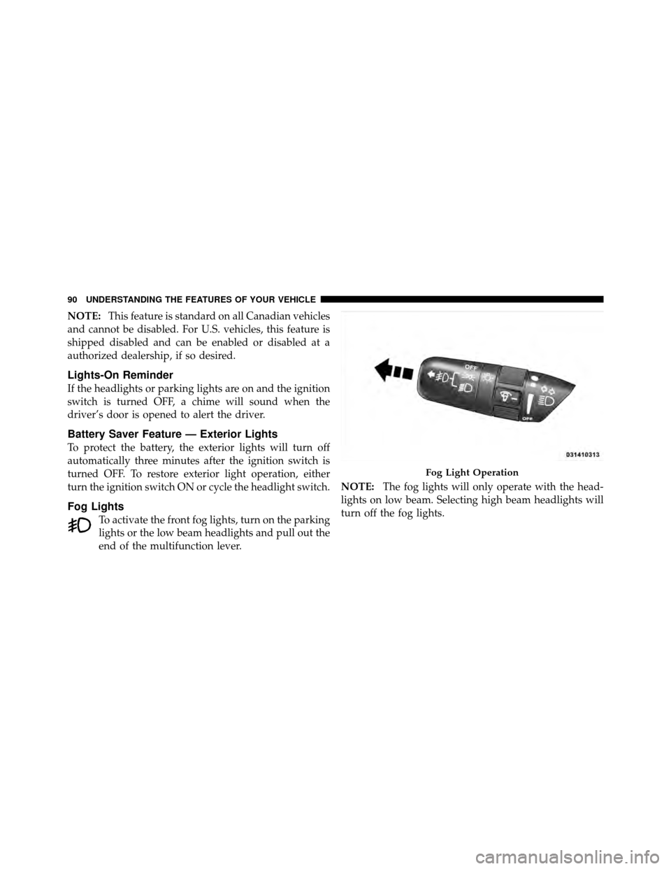
To activate the front fog lights, turn on the parking
lights or the low beam headlights and pull out the
end of the multifunction lever. NOTE:
The fog lights will only operate with the head-
lights on low beam. Selecting high beam headlights will
turn off the fog lights.
Fog Light Operation
90 UNDERSTANDING THE FEATURES OF YOUR VEHICLE
Page 95 of 315

Turn Signals
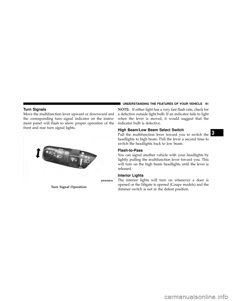
Move the multifunction lever upward or downward and
the corresponding turn signal indicator on the instru-
ment panel will flash to show proper operation of the
front and rear turn signal lights.NOTE:
If either light has a very fast flash rate, check for
a defective outside light bulb. If an indicator fails to light
when the lever is moved, it would suggest that the
indicator bulb is defective.
High Beam/Low Beam Select Switch
Pull the multifunction lever toward you to switch the
headlights to high beam. Pull the lever a second time to
switch the headlights back to low beam.
Flash-to-Pass
You can signal another vehicle with your headlights by
lightly pulling the multifunction lever toward you. This
will turn on the high beam headlights until the lever is
released.
Interior Lights
The interior lights will turn on whenever a door is
opened or the liftgate is opened (Coupe models) and the
dimmer switch is not in the defeat position.
Turn Signal Operation
3
UNDERSTANDING THE FEATURES OF YOUR VEHICLE 91
Page 113 of 315

Liquid Crystal Display (LCD) Panel
The LCD panel at the bottom of the speedometer displays
specific messages for given conditions. These messages
are as follows:
•The words “DOOR AJAR” will display if a door is not
closed completely. In addition, a single chime will
sound if you move the vehicle when a door is not
closed completely.
•The words “DOOR UNLOCKED” will flash in the
display if one door is unlocked and will remain on
steady if both doors are unlocked.
•The word “DECK” will flash in the display if the
trunk/liftgate is open.
•The words “LOW TIRE” will flash slowly in the
display and a chime will sound if the tire pressure is
low.
•The words “FLAT TIRE” will flash rapidly in the
display and a chime will sound if critically low tire
pressure is detected.
Message Center
When the appropriate conditions ex-
ist, the Message Center displays the
following indicators and warnings:
High Beam Light
This light will turn on when the high beam
headlights are on. Pull the Multifunction Lever on
the left side of the steering column toward you to switch
the headlights from low beam to high beam. Pull the
lever a second time to switch the headlights back to low
beam.
4
UNDERSTANDING YOUR INSTRUMENT PANEL 109
Page 254 of 315

properly. If not, there is a problem with a switch or the
system. See your authorized dealer for service.
•Cover the vehicle whenever possible to prevent acci-
dental damage to the finish.
REPLACEMENT BULBS
LIGHT BULBS – InteriorBulb Number
Message Center Indicators .................. 103
Cluster ................................ 103
Gauge Pack ............................ 103
Heater Control ........................... 37
Interior Lamp ......................... 212–2
Courtesy Foot Well Lights .................. 194
Cargo Lamp (Coupe Liftgate) ................ 168LIGHT BULBS – Exterior
(Convertible Models)
Bulb Number
Low/High Beam High Intensity Discharge
(HID) Headlamp .... Serviced at authorized dealer only
Auxiliary High Beam Headlamp .....(HB3A) 9005XS
Front Park/Turn Signal Lamp .............3157AK
Fog Lamp ....................... (H10 U) 9145
Front Side Marker Lamp .................. 2886X
Center High Mounted Stop Lamp
(CHMSL) ................ 16LED (not serviceable)
Tail/Stop Lamp ......................... 3157
Taillamp ............................... 194
Rear Marker Lamp ....................... 194
Backup Lamp .......................... 3157
Rear Turn Signal Lamp .................3457AK
License Lamp ........................... 168
250 MAINTAINING YOUR VEHICLE
Page 255 of 315

LIGHT BULBS – Exterior
(Coupe Models) Bulb Number
Low/High Beam High Intensity Discharge (HID)
Headlamp......... Ser viced at authorized dealer only
Auxiliary High Beam Headlamp .....(HB3A) 9005XS
Front Park/Turn Signal Lamp .............3157AK
Fog Lamp ....................... (H10 U) 9145
Front Side Marker Lamp .................. 2886X
Center High Mounted Stop Lamp (CHMSL) . . . 16 LED
(not serviceable)
Tail/Stop/Turn Signal Lamp ................3157
Rear Marker Lamp ....................... 194
Backup Lamp .......................... 3157
License Lamp ........................... 168
NOTE: Upon turning the High Intensity Discharge
(HID) Headlamps on, there is a blue hue to the lamps.
This diminishes and becomes more white after approxi-
mately 10 seconds as the system charges.BULB REPLACEMENT
Auxiliary High Beam Headlamp, Front Park/Turn
Signal Lamp, Front Side Marker Lamp
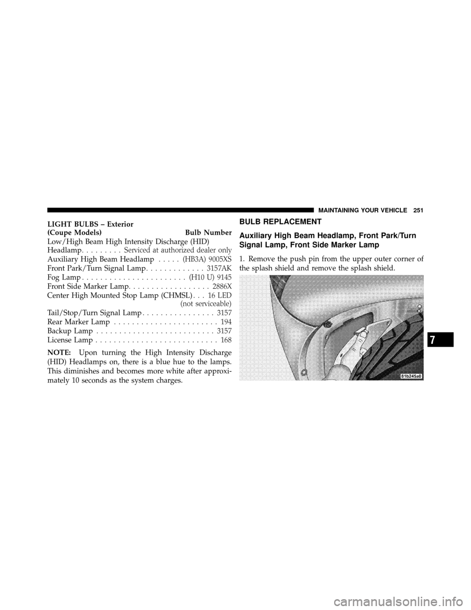
1. Remove the push pin from the upper outer corner of
the splash shield and remove the splash shield.
7
MAINTAINING YOUR VEHICLE 251
Page 256 of 315
2. Turn the appropriate bulb and socket assembly coun-
terclockwise, and then pull it out of the headlamp
assembly.3. Pull the bulb out of the socket assembly.
4. Push the replacement bulb into the socket assembly.
5. Reinstall the bulb and socket assembly into the head-
lamp assembly, and then turn it clockwise.
6. Install the splash shield and push pin.
High Intensity Discharge Headlamps (HID)
The headlamps are a type of high voltage discharge tube.
High voltage can remain in the circuit even with the
headlamp switch off and the key removed.
Because of
this, you should not attempt to service a headlamp bulb
yourself. If a headlamp bulb fails, take your vehicle to
an authorized dealer for service.
1 — Front Side Marker Lamp
2 — Front Park/Turn Signal Lamp
3 — Low/High Beam HID Headlamp
4 — Auxiliary High Beam Headlamp
5 — Headlamp Adjustment — Aim Up and Down
252 MAINTAINING YOUR VEHICLE