2010 DODGE DAKOTA radio
[x] Cancel search: radioPage 30 of 76

Guide Me Home
• Press the NAV hard-key to access the Navigation Main Menu.
• Touch the GUIDE ME HOME soft-key to route you back to your home destination fromyour current location. Touch the GO soft-key to start your trip.
Map
• Press the NAV hard-key to access the Navigation Main Menu.
• Touch the MAP soft-key to display a map of your current position.
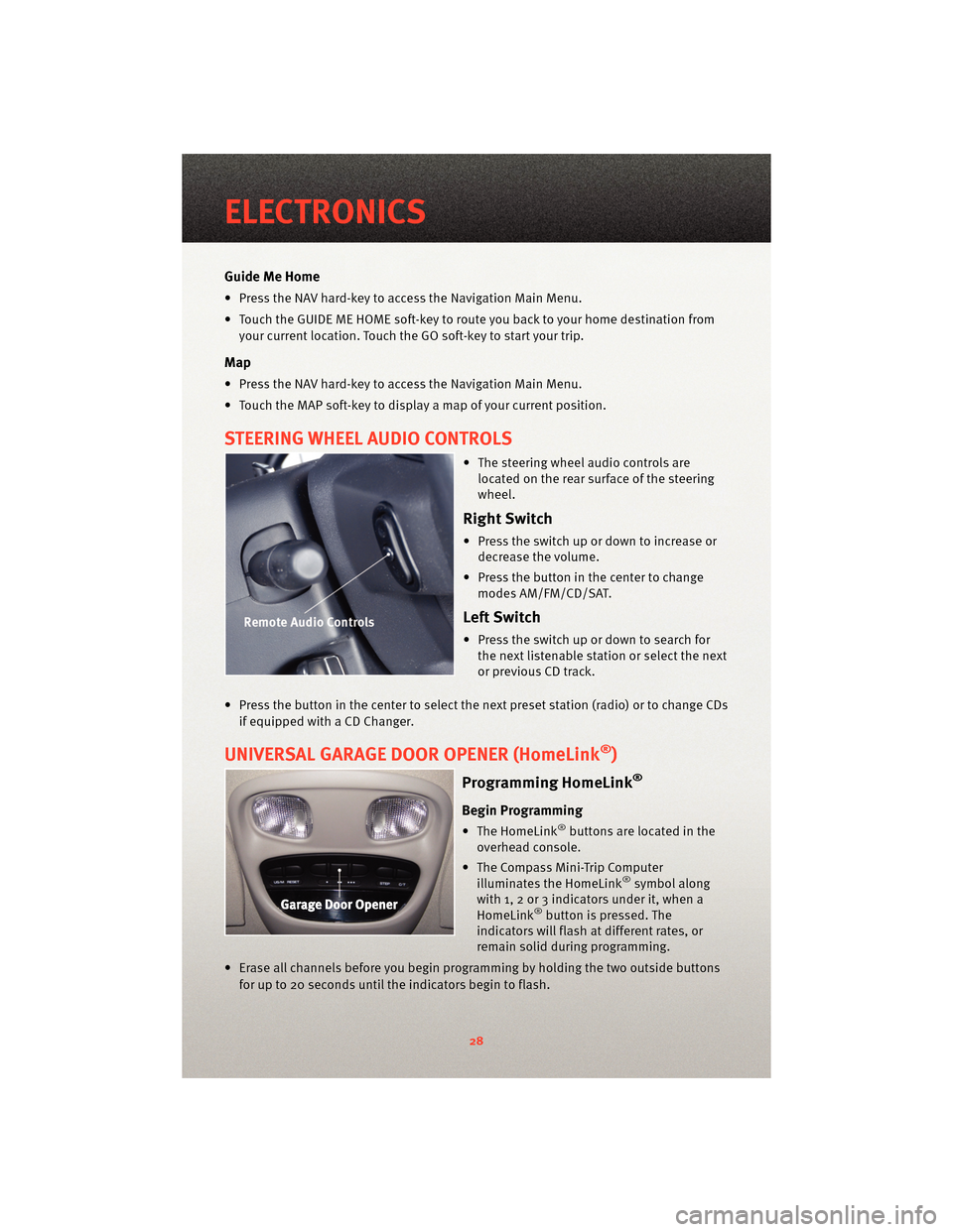
STEERING WHEEL AUDIO CONTROLS
• The steering wheel audio controls arelocated on the rear surface of the steering
wheel.
Right Switch
• Press the switch up or down to increase ordecrease the volume.
• Press the button in the center to change modes AM/FM/CD/SAT.
Left Switch
• Press the switch up or down to search forthe next listenable station or select the next
or previous CD track.
• Press the button in the center to select the next preset station (radio) or to change CDs if equipped with a CD Changer.
UNIVERSAL GARAGE DOOR OPENER (HomeLink®)
Programming HomeLink®
Begin Programming
• The HomeLink®buttons are located in the
overhead console.
• The Compass Mini-Trip Computer illuminates the HomeLink
®symbol along
with 1, 2 or 3 indicators under it, when a
HomeLink
®button is pressed. The
indicators will flash at different rates, or
remain solid during programming.
• Erase all channels before you begin progr amming by holding the two outside buttons
for up to 20 seconds until the indicators begin to flash.
ELECTRONICS
28
Page 34 of 76

Changing The Volume
• Start a dialogue by pressing the Phone button, then adjust the volume during a
normal call.
• Use the radio ON/OFF VOLUME rotary knob to adjust the volume to a comfortable level while the Uconnect™ system is speaking. Please note the volume setting for
Uconnect™ is different than the audio system.
NOTE: To access the tutorial, press the Uconnect™ hard-key. After the BEEP, say
“tutorial”. Press any hard-key or touch the display to cancel the tutorial.
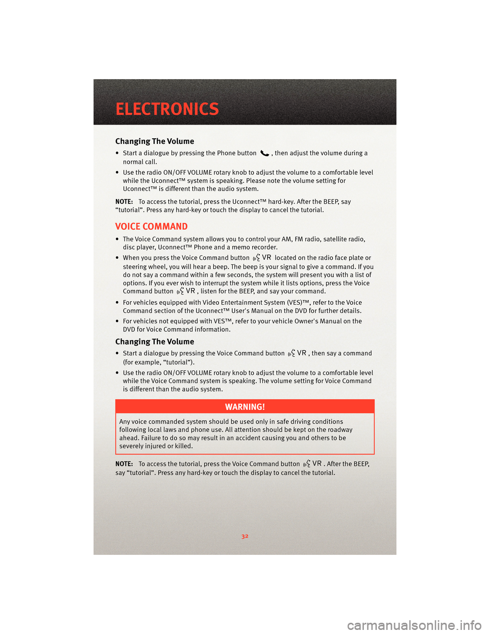
VOICE COMMAND
• The Voice Command system allows you to control your AM, FM radio, satellite radio, disc player, Uconnect™ Phone and a memo recorder.
• When you press the Voice Command button
located on the radio face plate or
steering wheel, you will hear a beep. The beep is your signal to give a command. If you
do not say a command within a few seconds, the system will present you with a list of
options. If you ever wish to interrupt the system while it lists options, press the Voice
Command button
, listen for the BEEP, and say your command.
• For vehicles equipped with Video Entertainment System (VES)™, refer to the Voice Command section of the Uconnect™ User's Manual on the DVD for further details.
• For vehicles not equipped with VES™, refer to your vehicle Owner's Manual on the DVD for Voice Command information.
Changing The Volume
• Start a dialogue by pressing the Voice Command button, then say a command
(for example, “tutorial”).
• Use the radio ON/OFF VOLUME rotary knob to adjust the volume to a comfortable level while the Voice Command system is speaking. The volume setting for Voice Command
is different than the audio system.
WARNING!
Any voice commanded system should be used only in safe driving conditions
following local laws and phone use. All attention should be kept on the roadway
ahead. Failure to do so may result in an accident causing you and others to be
severely injured or killed.
NOTE: To access the tutorial, press the Voice Command button
. After the BEEP,
say “tutorial”. Press any hard-key or touch the display to cancel the tutorial.
ELECTRONICS
32
Page 51 of 76

Preparations for Jump-Start
• The battery in your vehicle is located in the front of the engine compartment, behind
the left headlight assembly.
WARNING!
• Take care to avoid the radiator coolin g fan whenever the hood is raised. It can start
anytime the ignition switch is on. You can be injured by moving fan blades.
• Remove any metal jewelry, such as watch bands or bracelets, that might make an inadvertent electrical contact. You could be seriously injured.
• Batteries contain sulfuric acid that can burn your skin or eyes and generate hydrogen gas which is flammable and explosive. Keep open flames or sparks away
from the battery.
• Set the parking brake, shift the autom atic transmission into PARK and turn the ignition
to LOCK.
• Turn off the heater, radio, and all unnecessary electrical accessories.
• If using another vehicle to jump-start the battery, park the vehicle within the jumper cables reach, set the parking brake and make sure the ignition is OFF.
WARNING!
Do not allow vehicles to touch each other as this could establish a ground connection
and personal injury could result.
Jump-Starting Procedure
WARNING!
Failure to follow this procedure could result in personal injury or property damage due
to battery explosion.
CAUTION!
Failure to follow these procedures could result in damage to the charging system of
the booster vehicle or the discharged vehicle.
• Connect the positive (+)end of the jumper cable to the positive (+)post of the
discharged vehicle.
• Connect the opposite end of the positive (+)jumper cable to the positive (+)post of
the booster battery.
• Connect the negative end (-)of the jumper cable to the negative (-)post of the booster
battery.
49
WHAT TO DO IN EMERGENCIES
Page 65 of 76

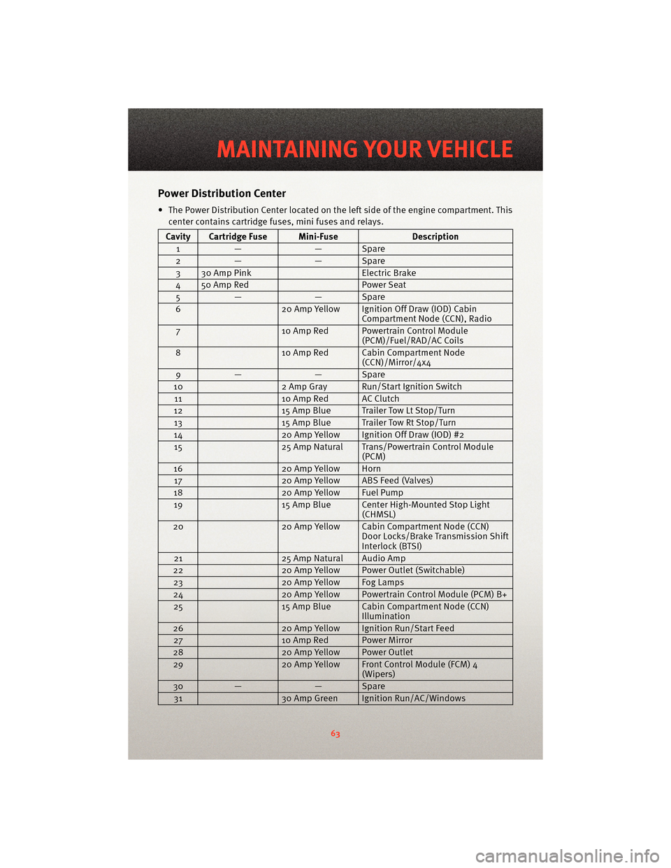
Power Distribution Center
• The Power Distribution Center located on theleft side of the engine compartment. This
center contains cartridge fuses, mini fuses and relays.
Cavity Cartridge Fuse Mini-Fuse Description
1 — — Spare
2 — — Spare
3 30 Amp Pink Electric Brake
4 50 Amp Red Power Seat
5 — — Spare
6 20 Amp Yellow Ignition Off Draw (IOD) Cabin
Compartment Node (CCN), Radio
7 10 Amp Red Powertrain Control Module
(PCM)/Fuel/RAD/AC Coils
8 10 Amp Red Cabin Compartment Node
(CCN)/Mirror/4x4
9 — — Spare
10 2 Amp Gray Run/Start Ignition Switch
11 10 Amp Red AC Clutch
12 15 Amp Blue Trailer Tow Lt Stop/Turn
13 15 Amp Blue Trailer Tow Rt Stop/Turn
14 20 Amp Yellow Ignition Off Draw (IOD) #2
15 25 Amp Natural Trans/Powertrain Control Module
(PCM)
16 20 Amp Yellow Horn
17 20 Amp Yellow ABS Feed (Valves)
18 20 Amp Yellow Fuel Pump
19 15 Amp Blue Center High-Mounted Stop Light
(CHMSL)
20 20 Amp Yellow Cabin Compartment Node (CCN)
Door Locks/Brake Tra nsmission Shift
Interlock (BTSI)
21 25 Amp Natural Audio Amp
22 20 Amp Yellow Power Outlet (Switchable)
23 20 Amp Yellow Fog Lamps
24 20 Amp Yellow Powertrain Control Module (PCM) B+
25 15 Amp Blue Cabin Compartment Node (CCN)
Illumination
26 20 Amp Yellow Ignition Run/Start Feed
27 10 Amp Red Power Mirror
28 20 Amp Yellow Power Outlet
29 20 Amp Yellow Front Control Module (FCM) 4
(Wipers)
30 — — Spare
31 30 Amp Green Ignition Run/AC/Windows
63
MAINTAINING YOUR VEHICLE
Page 69 of 76

CHRYSLER GROUP LLC
CUSTOMER CENTER
P.O. Box 21–8004
Auburn Hills, MI 48321–8004
Phone: 1–866–726–4636
CHRYSLER CANADA INC.
CUSTOMER CENTER
P.O. Box 1621
Windsor, Ontario N9A 4H6
Phone: 1–800–465–2001
ASSISTANCE FOR THE
HEARING IMPAIRED
• To assist customers who have hearingdifficulties, the manufacturer has
installed special TDD
(Telecommunication Devices for the
Deaf) equipment at its customer
center. Any hearing or speech
impaired customer, who has access to
a TDD or a conventional teletypewriter
(TTY) in the United States, can
communicate with the manufacturer
by dialing 1–800–380–CHRY.
Canadian residents with hearing
difficulties that requir e assistance can
use the special needs relay service
offered by Bell Canada. For TTY
teletypewriter users, dial 711 and for
Voice callers, dial 1–800–855–0511 to
connect with a Bell Relay Service
operator.
WARNING!
Engine exhaust, some of its
constituents, and certain vehicle
components contain, or emit,
chemicals known to the State of
California to cause cancer and birth
defects, or other reproductive harm.
In addition, certain fluids contained
in vehicles and certain products of
component wear contain, or emit,
chemicals known to the State of
California to cause cancer and birth
defects, or other reproductive harm.
PUBLICATIONS ORDERING
• If you are the first registered retail
owner of your vehicle, you may obtain
one free printed copy of the Owner's
Manual, Warranty Booklet or Radio
Manuals on your DVD by calling
1–877–726–4636 (U.S.) or
1–800–387–1143 (Canada) or by
contacting your dealer.
• Replacement User Guides or DVDs or, if you prefer, additional printed
copies of the Owner's Manual,
Warranty Booklet or Radio Manuals
may be purchased by visiting
www.techauthority.com or by calling
1–800–890–4038 (U.S.) or
1–800–387–1143 (Canada). Visa,
Master Card, American Express and
Discover orders are accepted. If you
prefer mailing your order, please call
the above numbers for an order form.
NOTE: A street address is required
when ordering manuals (no P.O. Boxes).
67
CONSUMER ASSISTANCE
Page 73 of 76

MOPAR®ACCESSORIES
• The following highlights just some of the authentic Dodge Truck Accessories byMOPAR®that have been engineered to customize your Dodge Dakota.
• To see the full line of accessories, sto p by your Dodge dealer or visitMOPAR.com.
CHROME:
• Exhaust Tip • Tubular Side Steps • Fuel Filler Door
• 18” chrome Cast Aluminum Wheel • Front Air Deflector • Grille
EXTERIOR:
• Under The Rail Bedliner • Side Window Air Deflectors• Fender Flares
• Fiberglass Tonneau Co ver • Bed Extender • Bed Mat
• Snapless Tonneau Cover • Tri-Fold Tonneau Cover • Tuner Style Tail lamps
• Molded Splash Guards • Hitch Receiver
INTERIOR:
• Premium Carpet Floor Mats • Door Sill Guards • Slush Mats
ELECTRONICS:
• Portable Navigation Systems • Uconnect™ Web (WiFi) • Sirius Satellite Radio
•iPod
®Adapter • Media Center 730N (RER
Navigation Radio)
CARRIERS:
• Bed Mounted Bike Carrier • Bed Mounted Cargo Basket With Cargo Net• Roof Mount Bike Carrier
• Bed Mounted Ski and Snowboard Carrier • Sport Utility Bars
(accommodates all
carriers) • Diamond Plate Toolbox
iPod
®is a registered trademark of Apple, Inc.
71
MOPAR ACCESSORIES