Page 195 of 530

Express Close
Press the switch forward and release, and the sunroof
will close automatically from any position. The sunroof
will close fully, then stop automatically. This is called
“Express Close”. During Express Close operation, any
movement of the sunroof switch will stop the sunroof.
WARNING!
Do not allow small children to operate the sunroof.
Never allow your fingers, other body parts, or any
object to project through the sunroof opening. Injury
may result.
Ignition Off Operation
The power sunroof switch will remain active for 10 min-
utes after the ignition switch is turned OFF. Opening
either front door will cancel this feature.
Auto-Express with Anti-Pinch Protection
During express closing, anytime an obstacle that restricts
glass movement is detected, the motor will stop and
reverse travel to avoid pinching the object.
Auto Express will stop and reverse travel up to three
times in succession. After the third time, Auto Express
will enter a manual operation mode. This allows the
operator to manually control the power switch, in order
to close or open the sunroof in case of a malfunction.
Wind Buffeting
Wind buffeting can be described as the perception of
pressure on the ears or a helicopter-type sound in the
ears. Your vehicle may exhibit wind buffeting with the
windows down, or the sunroof (if equipped) in certain
open or partially open positions. This is a normal occur-
rence and can be minimized. If the buffeting occurs with
the rear windows open, open the front and rear windows
together to minimize the buffeting. If the buffeting occurs
194 UNDERSTANDING THE FEATURES OF YOUR VEHICLE
ProCarManuals.com
Page 196 of 530

with the sunroof open, adjust the sunroof opening to
minimize the buffeting or open any window.
Sunroof Maintenance
Use only a non-abrasive cleaner and a soft cloth to clean
the glass panel.
ELECTRICAL POWER OUTLETS — IF EQUIPPED
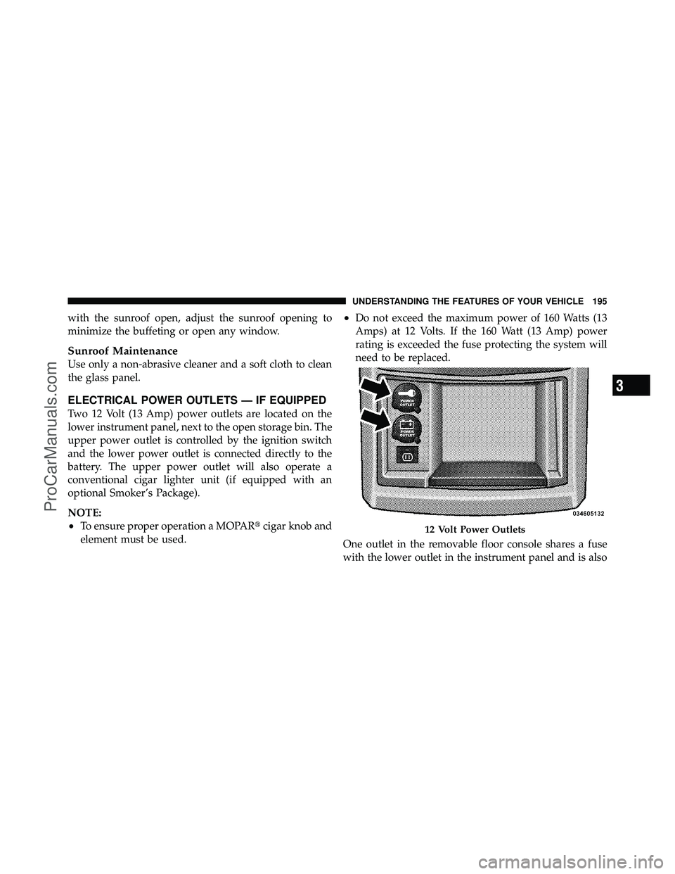
Two 12 Volt (13 Amp) power outlets are located on the
lower instrument panel, next to the open storage bin. The
upper power outlet is controlled by the ignition switch
and the lower power outlet is connected directly to the
battery. The upper power outlet will also operate a
conventional cigar lighter unit (if equipped with an
optional Smoker’s Package).
NOTE:
•To ensure proper operation a MOPAR�cigar knob and
element must be used.
•Do not exceed the maximum power of 160 Watts (13
Amps) at 12 Volts. If the 160 Watt (13 Amp) power
rating is exceeded the fuse protecting the system will
need to be replaced.
One outlet in the removable floor console shares a fuse
with the lower outlet in the instrument panel and is also
12 Volt Power Outlets
3
UNDERSTANDING THE FEATURES OF YOUR VEHICLE 195
ProCarManuals.com
Page 216 of 530

ROOF LUGGAGE RACK — IF EQUIPPED
The crossbars and side rails are designed to carry the
weight on vehicles equipped with a luggage rack. The
load must not exceed 150 lbs (68 kg), and should be
uniformly distributed over the luggage rack crossbars.
Distribute cargo weight evenly on the roof rack crossbars.
The roof rack does not increase the total load carrying
capacity of the vehicle. Be sure the total load of cargo
inside the vehicle plus that on the external rack does not
exceed the maximum vehicle load capacity.
To move the crossbars, loosen the thumb screws located
at the upper edge of each crossbar approximately six
turns, then move the crossbar to the desired position,
keeping the crossbars parallel to the rack frame. Once the
crossbar is in place, retighten the thumb screws to lock
the crossbar into position.Attempt to move the crossbar again to ensure that it has
properly locked into position.
NOTE:
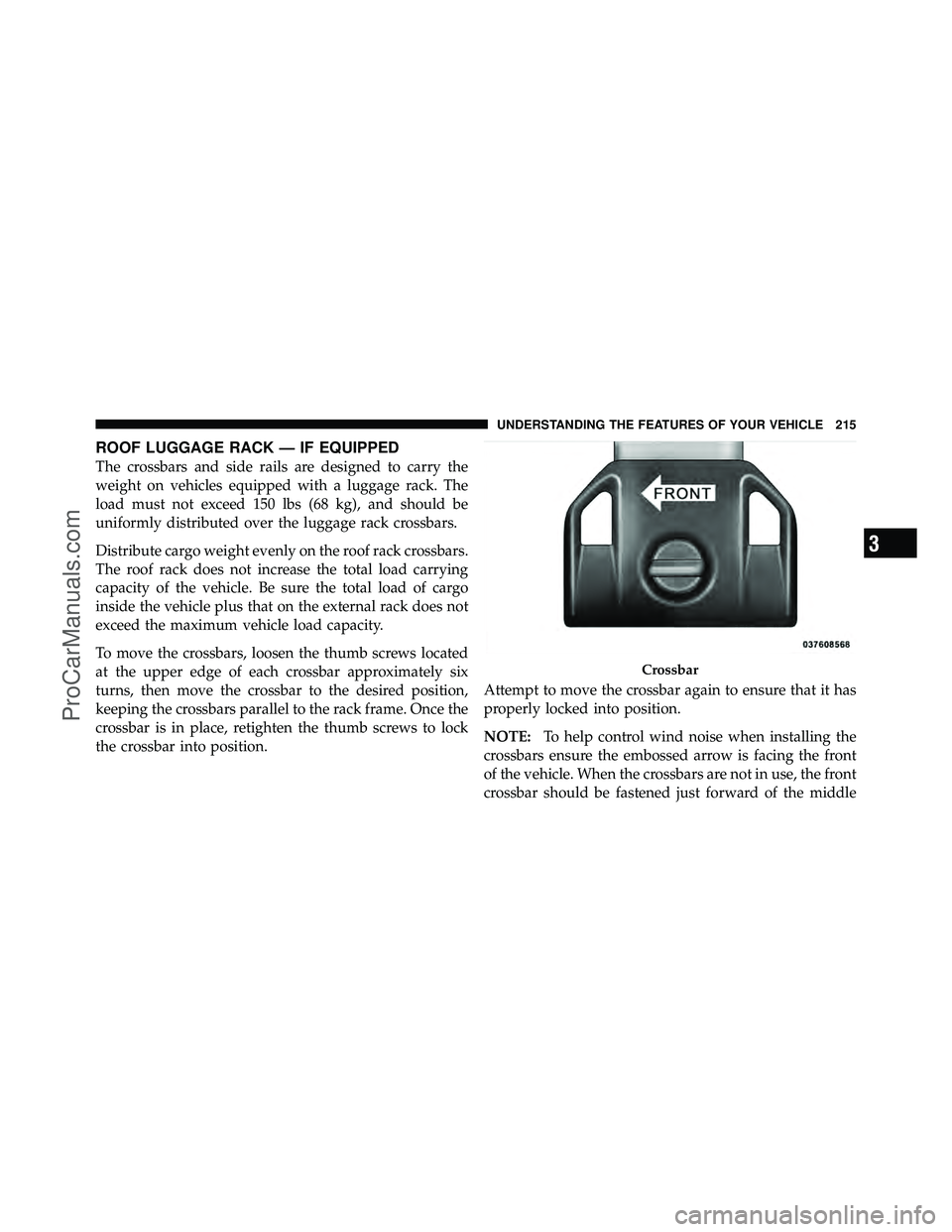
To help control wind noise when installing the
crossbars ensure the embossed arrow is facing the front
of the vehicle. When the crossbars are not in use, the front
crossbar should be fastened just forward of the middle
Crossbar
3
UNDERSTANDING THE FEATURES OF YOUR VEHICLE 215
ProCarManuals.com
Page 217 of 530

support and the rear crossbar should be fastened at the
rearmost position of the side rails. This will help reduce
the amount of wind noise when the crossbars are not in
use.
The tie down holes on the crossbar ends should always
be used to tie down the load. Check the straps frequently
to be sure that the load remains securely attached.
CAUTION!
•Crossbars should remain equally spaced or paral-
lel at any luggage rack position for proper func-
tion. Noncompliance could result in damage to the
luggage rack, cargo and/or vehicle.(Continued)
CAUTION! (Continued)
•To avoid damage to the roof rack and vehicle, do
not exceed the maximum roof rack load capacity of
150 lbs (68 kg). Always distribute heavy loads as
evenly as possible and secure the load appropri-
ately.
•Long loads which extend over the windshield,
such as wood panels or surfboards, or loads with
large frontal area should be secured to both the
front and rear of the vehicle.
•Travel at reduced speeds and turn corners care-
fully when carrying large or heavy loads on the
roof rack. Wind forces, due to natural causes or
nearby truck traffic, can add sudden upward lift to
a load. This is especially true on large flat loads
and may result in damage to the cargo or your
vehicle.
216 UNDERSTANDING THE FEATURES OF YOUR VEHICLE
ProCarManuals.com
Page 218 of 530
WARNING!
Cargo must be securely tied before driving your
vehicle. Improperly secured loads can fly off the
vehicle, particularly at high speeds, resulting in per-
sonal injury or property damage. Follow the Roof
Rack Cautions when carrying cargo on your roof
rack.
SUN SCREENS — IF EQUIPPED
Sun screens are available for second and third row
seating windows. The screens store in the sill trim panels,
and the tops of the windows are equipped with hooks
that the sun screens attach to when pulled out.
Sun Screen Retracted
3
UNDERSTANDING THE FEATURES OF YOUR VEHICLE 217
ProCarManuals.com
Page 256 of 530

Tilt MIRR. In Reverse
When this feature is selected and the vehicle is placed in
a reverse gear, the driver’s side mirror will tilt downward
to allow the driver to see into the previous blind spot and
avoid objects in close proximity to the rear of the vehicle.
Key-Off Power Delay
When this feature is selected, the power window
switches, radio, Uconnect™ Phone (if equipped), DVD
video system (if equipped), power sunroof (if equipped),
and power outlets will remain active for up to 10 minutes
after the ignition switch is turned OFF. Opening a vehicle
door will cancel this feature. To make your selection,
press and release the RESET button until Off, 45 sec.,
5 min., or 10 min. appears.
ILLUMIN. Approach
When this feature is selected, the headlights will activate
and remain on for up to 90 seconds when the doors areunlocked with the RKE transmitter. To make your selec-
tion, press and release the RESET button until “OFF,”
“30 sec.,” “60 sec.,” or “90 sec.” appears.
Blind Spot Alert
There are three selections when operating Blind Spot
Alert. By pressing and releasing the RESET button once,
the Blind Spot Alert feature can be activated in “Blind
Spot Alert Lights” mode. When this mode is selected the
Blind Spot Monitor (BSM) system is activated and will
only show a visual alert in the outside mirrors. By
pressing and releasing the RESET button a second time
“Blind Spot Alert Lights/CHM” mode is activated. In
this mode the Blind Spot Monitor (BSM) will show a
visual alert in the outside mirrors as well as an audible
alert when the turn signal is on. When “Blind Spot Alert
Off” is selected the Blind Spot Monitor (BSM) system is
deactivated.
4
UNDERSTANDING YOUR INSTRUMENT PANEL 255
ProCarManuals.com
Page 290 of 530

information, call the toll-free number 888-539-7474, or
visit the Sirius web site at www.sirius.com, or at www-
.siriuscanada.ca for Canadian residents.
Electronic Serial Number/Sirius Identification
Number (ESN/SID)
Please have the following information available when
calling:
1. The Electronic Serial Number/Sirius Identification
Number (ESN/SID).
2. Your Vehicle Identification Number.
To access the ESN/SID, refer to the following steps:
ESN/SID Access With RES Radios
With the ignition switch in the ON/RUN or ACC posi-
tion and the radio on, press the SETUP button and scroll
using the TUNE/SCROLL control knob until Sirius ID is
selected. Press the TUNE/SCROLL control knob and theSirius ID number will display. The Sirius ID number
display will time out in two minutes. Press any button on
the radio to exit this screen.
ESN/SID Access With REN/RER/RBZ Radios
While in SAT mode, press the MENU button on the radio
faceplate.
Next, touch the SUBSCRIPTION tab on the touch screen.
All the ESNs that apply to your vehicle will display.
Selecting Uconnect™ Multimedia (Satellite) Mode
Press the SAT button until
�SAT�appears in the display. A
CD may remain in the radio while in the Satellite radio
mode.
Satellite Antenna
To ensure optimum reception, do not place items on the
roof around the rooftop antenna location. Metal objects
placed within the line of sight of the antenna will cause
decreased performance. Larger luggage items such as
4
UNDERSTANDING YOUR INSTRUMENT PANEL 289
ProCarManuals.com
Page 351 of 530

Tire Terminology and Definitions
TermDefinition
B-Pillar The vehicle B-Pillar is a structural member of the body located
between the front and rear door (of a four-door vehicle) running
from the sill to the roof.
Cold Tire Pressure Cold tire inflation pressure is defined as the tire pressure after the
vehicle has not been driven for at least 3 hours, or driven less
than 1 mile (1.6 km) after sitting for a three hour period. Inflation
pressure is measured in units of PSI (pounds per square inch) or
KPa (kilopascals).
Maximum Inflation Pressure The maximum inflation pressure is the maximum permissible cold
tire inflation pressure for this tire. The max inflation pressure is
molded into the sidewall.
Recommended Inflation Pressure Vehicle manufacturer’s recommended tire inflation pressure as
shown on the tire placard.
Tire Placard A paper label permanently attached to the vehicle showing the
vehicle’s loading capacity, the original equipment tire size and the
recommended inflation pressure.
350 STARTING AND OPERATING
ProCarManuals.com