Page 49 of 92

WARNING!
To Avoid Serious Injury or Death: Do not use a three-prong adaptor. Do not insert
any objects into the receptacles. Do not touch with wet hands. Close the lid when
not in use. If this outlet is mishandled, it may cause an electric shock and failure.
POWER OUTLETS
• There are four 12 Volt power outlets in your vehicle.
• Two are located on the lower instrument panel, next to the open storage bin. Theupper power outlet is controlled by the ignition switch and the lower power outlet
is connected directly to the battery.
• One is located in the removable floor console and is also connected directly to the battery.
• One is located in the rear quarter panel near the liftgate. This outlet is also controlled by the ignition switch.
NOTE: Do not exceed the maximum power of 160 Watts (13 Amps) at 12 Volts. If the
160 Watt (13 Amp) power rating is exceeded the fuse protecting the system will need
to be replaced.
Uconnect™ Phone
• The Uconnect™ Phone is a voice-activated, hands-free, in-vehicle communications system.
• The Uconnect™ Phone allows you to dial a phone number with your cellular phone using simple voice commands.
• For vehicles equipped with Video Entertainment System (VES)™, refer to the Uconnect™ Phone section of the Uconnect™ User’s Manual on the DVD for further
details.
• For vehicles not equipped with VES™, refer to your vehicle Owner’s Manual on the DVD for further details.
WARNING!
• Any voice commanded system should be used only in safe driving conditionsfollowing local laws and phone use. All attention should be kept on the roadway
ahead. Failure to do so may result in an accident causing you and others to be
severely injured or killed.
• In an emergency to use Uconnect™ Phone, your cellular phone must be: • turned on,
• paired to Uconnect™ Phone,
• and have network coverage.
NOTE: The Uconnect™ Phone requires a cellular phone equipped with the
47
ELECTRONICS
Page 50 of 92

Bluetooth®Hands-Free Profile, Version 0.96 or higher. For Uconnect™ customer
support, call 1–877–855–8400.
Phone Pairing
NOTE: Pairing is a one-time initial setup before using the phone. You will also need
to follow the Bluetooth®instructions in your cell phone user guide to complete the
phone pairing setup.
• Press the Phone button
to begin.
• Wait for the “ready” prompt and beep.
• (After the BEEP), say “Uconnect setup”.
• (After the BEEP), say “phone pairing”.
• (After the BEEP), say “pair a phone”.
• Follow the audible prompts.
• You will be asked to enter a four-digit Personal Identification Number (PIN), which you will later need to enter into your cellular phone. You can enter any four-digit
PIN. You will not need to remember this PIN after the initial pairing process.
• You will then be prompted to give the phone pairing a name (each phone paired should have a unique name).
• Next you will be asked to give this new pairing a priority of 1 thru 7 (up to seven phones may be paired).
Making A Phone Call
• Press the Phone button.
• (After the BEEP), say “dial” (or “call” to a name).
• (After the BEEP), say number (or name).
Phonebook (Uconnect™ Local) Edit
• Press the Phone button.
• (After the BEEP), say “phonebook”.
• (After the BEEP), say “new entry” or “list names” or “delete”.
• Follow the prompts.
Receiving A Call – Accept (And End)
• When an incoming call rings/is announced on Uconnect™, press the Phone button
.
• To end a call, press the Phone button
.
Mute (Or Unmute) Microphone During Call
• During a call, press the Voice Command button.
• (After the BEEP), say “mute on” (or “mute off”).
ELECTRONICS
48
Page 51 of 92
, say “transfer call”.
Changing The Volume
• Start a dialogue by pressing")
Transfer Ongoing Call Between Handset And Vehicle
• During a call, press the Voice Command button.
• (After the BEEP), say “transfer call”.
Changing The Volume
• Start a dialogue by pressing the Phone button, then adjust the volume during
a normal call.
• Use the radio ON/OFF VOLUME rotary knob to adjust the volume to a comfortable level while the Uconnect™ system is speaking. Please note the volume setting for
Uconnect™ is different than the audio system.
NOTE: To access the tutorial, press the Uconnect™ hard-key. After the BEEP, say
“tutorial”. Press any hard-key or touch the display to cancel the tutorial.
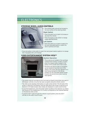
VOICE COMMAND
• The Voice Command system allows you to control your AM, FM radio, satellite radio, disc player, Uconnect™ Phone and a memo recorder.
• When you press the Voice Command button
located on the radio face plate
or steering wheel, you will hear a beep. The beep is your signal to give a command.
If you do not say a command within a few seconds, the system will present you with
a list of options. If you ever wish to interrupt the system while it lists options, press
the Voice Command button
, listen for the BEEP, and say your command.
• For vehicles equipped with Video Entertainment System (VES)™, refer to the Voice Command section of the Uconnect™ User’s Manual on the DVD for further details.
• For vehicles not equipped with VES™, refer to your vehicle Owner’s Manual on the DVD for Voice Command information.
Changing The Volume
• Start a dialogue by pressing the Voice Command button, then say a
command (for example, “tutorial”).
• Use the radio ON/OFF VOLUME rotary knob to adjust the volume to a comfortable level while the Voice Command system is speaking. The volume setting for Voice
Command is different than the audio system.
WARNING!
Any voice commanded system should be used only in safe driving conditions
following local laws and phone use. All attention should be kept on the roadway
ahead. Failure to do so may result in an accident causing you and others to be
severely injured or killed.
NOTE: To access the tutorial, press the Voice Command button
. After the
BEEP, say “tutorial”. Press any hard-key or touch the display to cancel the tutorial.
49
ELECTRONICS
Page 52 of 92
IN-FLOOR STORAGE –
STOW N’ GO®
Second Row Seat Storage
Bins
• Storage bins are located in the floorin front of the second row seats that
can be used when the second row
seat is in the upright position. Pull up
on the storage bin latch to open the
cover. Slide the storage bin locking
mechanism to the “Lock“ position to
allow greater access to the storage
bin.
WARNING!
In an accident, serious injury could
result if the seat storage bin covers
are not properly latched. DO NOT
drive the vehicle with the storage
bin covers open. Keep the storage
bin covers closed and latched while
the vehicle is in motion. DO NOT use
a storage bin latch as a tie down.
Cargo Area Storage
• The liftgate sill plate has a raised line
with the statement “Load To This
Line”. This line indicates how far
rearward cargo can be placed
without interfering with liftgate
closing.
UTILITY
50
Page 53 of 92

Engine/TransaxleGCWR (Gross
Combined Wt. Rating) Frontal AreaMax. GTW
(Gross Trailer Wt.) Max. Tongue Wt.
(See Note)
3.3L, 3.8L and
4.0L/Automat")
TRAILER TOWING WEIGHTS (MAXIMUM TRAILER WEIGHT RATINGS)
Engine/TransaxleGCWR (Gross
Combined Wt. Rating) Frontal AreaMax. GTW
(Gross Trailer Wt.) Max. Tongue Wt.
(See Note)
3.3L, 3.8L and
4.0L/Automatic 7,000lbs(3175kg) 22sqft(2.0sqm)
1,800 lbs (816 kg)
which includes up to 2 persons & Luggage 180 lbs (82 kg)
7,000lbs(3175kg) 22sqft(2.0sqm) 1,350 lbs (612 kg)
which includes 3 to 5 persons & Luggage 135 lbs (61 kg)
7,000lbs(3175kg) 22sqft(2.0sqm) 1,000 lbs (454 kg)
which includes 6 to 7 persons & Luggage 100 lbs (45 kg)
3.8L and
4.0L/Automatic (with
Tow Package) 9,000lbs(4082kg) 40sqft(3.72sqm)
3,800 lbs (1 723 kg)*
which includes up to 2 persons & Luggage 380 lbs (172 kg)
9,000lbs(4082kg) 40sqft(3.72sqm) 3,350 lbs (1 519 kg)*
which includes 3 to 5 persons & Luggage 335 lbs (152 kg)
9,000lbs(4082kg) 40sqft(3.72sqm) 3,000 lbs (1 360 kg)*
which includes 6 to 7 persons & Luggage 300 lbs (136 kg)
*Vehicles equipped with Fold-in-Floor seating, the Gross Trailer Weight must be reduced by 100 lbs (45 kg). Refer to local
laws for maximum trailer towing speeds.
NOTE: The trailer tongue weight must be considered as part of the combined weight of occupants and cargo, and
should never exceed the weight referenced on the Tire and Loading Information placard.
51
UTILITY
Page 54 of 92

CAUTION!
Towing this vehicle behind another
vehicle (flat-towing with all four
wheels on the ground) is not
recommended.
NOTE: If the vehicle requires towi")
RECREATIONAL TOWING
(BEHIND MOTORHOME,
ETC.)
CAUTION!
Towing this vehicle behind another
vehicle (flat-towing with all four
wheels on the ground) is not
recommended.
NOTE: If the vehicle requires towing,
make sure all four wheels are off the
ground.
BRAKE/TRANSAXLE
INTERLOCK MANUAL
OVERRIDE
• The manual override may be used in the event that the shift lever should
fail to move from PARK with the Key
Fob in the ON position and the brake
pedal pr essed.
• To operate the shift lock manual override, perform the following
steps: • Remove the cover located to the
top right of the shift lever in the
instrument panel.
• The override can be activated by pressing the white-colored tab,
which can be acc essedthrough
the hole in the instrument panel.
• While the override is pressed, the
shift lever can be moved out of
the PARK position without
pressing the brake pedal. After
operation, return the cover to its
original position.
• Have your vehicle inspected by your local authorized dealer immediately
if the shift lock manual override has
been used.
NOTE: If a malfunction occurs, the
system will trap the Key Fob in the
ignition cylinder to warn you that this
safety feature is inoperable. The
engine can be started and stopped, but
the Key Fob cannot be removed until
you obtain service.
UTILITY
52
Page 55 of 92

24-HOUR TOWING ASSISTANCE - U.S. ONLY
• Dial toll-free 1-800-521-2779 or 1-800-363-4869 for Canadian residents.
• Provide your name, vehicle identification number and license plate number.
• Provide your location, including telephone number, from which you are calling.
• Briefly describe the nature of the problem and answer a few simple questions.
• You will be given the name of the service provider and an estimated time of arrival.If you feel you are in an “unsafe situation”, please let us know. With your consent,
we will contact local police or safety authorities.
INSTRUMENT CLUSTER WARNING LIGHTS
- Electronic Stability Program (ESP) Indicator Light
• If this indicator light flashes during acceleration, apply as little throttle as possible.While driving, ease up on the accelerator. Adapt your speed and driving to the
prevailing road conditions. To improve the vehicle’s traction when starting off in
deep snow, sand or gravel, it may be desirable to switch the ESP system off.
- Tire Pressure Monitoring System (TPMS) Light
• Each tire, including the spare (if provided), should be checked monthly, when coldand inflated to the inflation pressure recommended by the vehicle manufacturer on
the vehicle placard or tire inflation pressure label. (If your vehicle has tires of a
different size than the size indicated on the vehicle placard or tire inflation
pressure label, you should determine the proper tire inflation pressure for those
tires.)
• As an added safety feature, your vehicle has been equipped with a Tire Pressure Monitoring System (TPMS) that illuminates a low tire pressure telltale when one or
more of your tires is significantly under-inflated. Accordingly, when the low tire
pressure telltale illuminates, you should stop and check your tires as soon as
possible, and inflate them to the proper pressure. Driving on a significantly
under-inflated tire causes the tire to overheat and can lead to tire failure.
Under-inflation also reduces fuel efficiency and tire tread life, and may affect the
vehicle’s handling and stopping ability.
• Please note that the TPMS is not a substitute for proper tire maintenance, and it is the driver’s responsibility to maintain correct tire pressure, even if under-inflation
has not reached the level to trigger illumination of the TPMS low tire pressure
telltale.
• Your vehicle has also been equipped with a TPMS malfunction indicator to indicate when the system is not operating properly. The TPMS malfunction indicator is
combined with the low tire pressure telltale. When the system detects a
malfunction, the telltale will flash for approximately one minute and then remain
continuously illuminated. This sequence will continue upon subsequent vehicle
start-ups as long as the malfunction exists.
53
WHAT TO DO IN EMERGENCIES
Page 56 of 92

• When the malfunction indicator is illuminated, the system may not be able todetect or signal low tire pressure as intended. TPMS malfunctions may occur for a
variety of reasons, including the installation of replacement or alternate tires or
wheels on the vehicle that prevent the TPMS from functioning properly. Always
check the TPMS malfunction telltale after replacing one or more tires or wheels on
your vehicle, to ensure that the replacement or alternate tires and wheels allow the
TPMS to continue to function properly.
CAUTION!
The TPMS has been optimized for the original equipment tires and wheels. TPMS
pressures and warning have been established for the tire size equipped on your
vehicle. Undesirable system operation or sensor damage may result when using
replacement equipment that is not of the same size, type, and/or style.
Aftermarket wheels can cause sensor damage. Do not use tire sealant from a can,
or balance beads if your vehicle is equipped with a TPMS, as damage to the
sensors may result.
- Engine Temperature Warning Light
• This light warns of an overheated engine condition.
• If the light turns on or flashes continuously while driving, safely pull over and stopthe vehicle. If the A/C system is on, turn it off. Also, shift the transmission into
NEUTRAL and idle the vehicle. If the temperature reading does not return to
normal, turn the engine off immediately and call for service.
• We recommend that you do not operate the vehicle or engine damage will occur. Have the vehicle serviced immediately.
WARNING!
A hot engine cooling system is dangerous. You or others could be badly burned by
steam or boiling coolant. You may want to call an authorized dealership for service
if your vehicle overheats.
- Brake Warning Light
• The Brake Warning light illuminates when there is either a system malfunction orthe parking brake is applied. If the light is on and the parking brake is not applied, it
indicates a possible brake hydraulic malfunction, brake booster problem or an
Anti-Lock Brake System problem.
• We recommend you drive to the nearest service center and have the vehicle serviced immediately.
WHAT TO DO IN EMERGENCIES
54