Page 116 of 436
TILT/TELESCOPING STEERING COLUMN
This feature allows you to tilt the steering column
upward or downward. It also allows you to lengthen or
shorten the steering column. The tilt/telescoping control
handle is located below the steering wheel at the end of
the steering column.To unlock the steering column, pull the control handle
outward. To tilt the steering column, move the steering
wheel upward or downward as desired. To lengthen or
shorten the steering column, pull the steering wheel
outward or push it inward as desired. To lock the steering
column in position, push the control handle inward until
fully engaged.
WARNING!
Do not adjust the steering wheel while driving. The
telescoping adjustment must be locked while driv-
ing. Adjusting the steering wheel while driving or
driving without the telescoping adjustment locked
could cause the driver to lose control of the vehicle.
Tilt/Telescoping Steering Wheel Lock
116 UNDERSTANDING THE FEATURES OF YOUR VEHICLE
Page 117 of 436

ELECTRONIC SPEED CONTROL — IF EQUIPPED
When engaged, the Electronic Speed Control takes over
the accelerator operation at speeds greater than 25 mph
(40 km/h).
The Electronic Speed Control lever is located on the right
side of the steering wheel.NOTE:
In order to ensure proper operation, the Elec-
tronic Speed Control System has been designed to shut
down if multiple Speed Control functions are operated
simultaneously. If this occurs, the Electronic Speed Con-
trol System can be reactivated by pushing the Electronic
Speed Control ON/OFF button and resetting the desired
vehicle set speed.
To Activate
Push and release the ON/OFF button located
on the end of the Electronic Speed Control
lever. The CRUISE indicator in the instrument
cluster will illuminate. To turn the system off,
push and release the ON/OFF button a second time. The
CRUISE indicator will turn off. Be sure to turn the system
off when not in use.
NOTE: The Electronic Speed Control system will auto-
matically turn off when the ignition is turned OFF.
Electronic Speed Control Lever
3
UNDERSTANDING THE FEATURES OF YOUR VEHICLE 117
Page 156 of 436

25. Tire Pressure Monitoring Telltale Light
Each tire, including the spare (if provided),
should be checked monthly, when cold and
inflated to the inflation pressure recommended
by the vehicle manufacturer on the vehicle
placard or tire inflation pressure label. (If your vehicle has
tires of a different size than the size indicated on the
vehicle placard or tire inflation pressure label, you should
determine the proper tire inflation pressure for those tires.)
As an added safety feature, your vehicle has been
equipped with a Tire Pressure Monitoring System
(TPMS) that illuminates a low tire pressure telltale when
one or more of your tires is significantly under-inflated.
Accordingly, when the low tire pressure telltale illumi-
nates, you should stop and check your tires as soon as
possible, and inflate them to the proper pressure. Driving
on a significantly under-inflated tire causes the tire to
overheat and can lead to tire failure. Under-inflation also
reduces fuel efficiency and tire tread life, and may affect
the vehicle’s handling and stopping ability. Please note that the TPMS is not a substitute for proper
tire maintenance, and it is the driver ’s responsibility to
maintain correct tire pressure, even if under-inflation has
not reached the level to trigger illumination of the TPMS
low tire pressure telltale.
Your vehicle has also been equipped with a TPMS
malfunction indicator to indicate when the system is not
operating properly. The TPMS malfunction indicator is
combined with the low tire pressure telltale. When the
system detects a malfunction, the telltale will flash for
approximately one minute and then remain continuously
illuminated. This sequence will continue upon subse-
quent vehicle start-ups as long as the malfunction exists.
When the malfunction indicator is illuminated, the sys-
tem may not be able to detect or signal low tire pressure
as intended. TPMS malfunctions may occur for a variety
of reasons, including the installation of replacement or
alternate tires or wheels on the vehicle that prevent the
TPMS from functioning properly. Always check the
156 UNDERSTANDING YOUR INSTRUMENT PANEL
Page 157 of 436

TPMS malfunction telltale after replacing one or more
tires or wheels on your vehicle, to ensure that the
replacement or alternate tires and wheels allow the TPMS
to continue to function properly.
CAUTION!
The TPMS has been optimized for the original
equipment tires and wheels. TPMS pressures and
warning have been established for the tire size
equipped on your vehicle. Undesirable system opera-
tion or sensor damage may result when using re-
placement equipment that is not of the same size,
type, and/or style. Aftermarket wheels can cause
sensor damage. Do not use tire sealant from a can, or
balance beads if your vehicle is equipped with a
TPMS, as damage to the sensors may result.26. Malfunction Indicator Light (MIL)
The Malfunction Indicator Light (MIL) is part of
an onboard diagnostic system called OBD that
monitors emissions, engine, and automatic trans-
axle control systems. The light will illuminate when the
key is in the ON position before engine start. If the bulb
does not come on when turning the key from LOCK to
ON, have the condition checked promptly.
Certain conditions such as a loose or missing gas cap,
poor fuel quality, etc., may illuminate the light after
engine start. The vehicle should be serviced if the light
stays on through several of your typical driving cycles. In
most situations, the vehicle will drive normally and will
not require towing.4
UNDERSTANDING YOUR INSTRUMENT PANEL 157
Page 159 of 436
WARNING!
In some circumstances a Transmission Temperature
Indicator, under continued operation, could cause the
fluid to boil over, come in contact with hot engine or
exhaust components and cause a fire.
28. High Beam Indicator This light indicates that the headlights are on high
beam. Pull the turn signal lever toward the steer-
ing wheel to switch the headlights to low beam.
29. Electronic Vehicle Information Center (EVIC)
Display — If Equipped
This display shows the EVIC messages when the appro-
priate conditions exist. Refer to “Electronic Vehicle Infor-
mation Center (EVIC)” in this section for more
information.
ELECTRONIC VEHICLE INFORMATION CENTER
(EVIC) – IF EQUIPPED
The Electronic Vehicle Information Center (EVIC) fea-
tures a driver-interactive display that is located in the
instrument cluster.
Electronic Vehicle Information Center (EVIC)
4
UNDERSTANDING YOUR INSTRUMENT PANEL 159
Page 215 of 436
Audio/Video RCA Jacks (AUX Jacks)
on the rear of the center console enable
the monitor to display video directly
from a video camera, connect video
games for display on the screen, or
play music directly from an MP3
player.
1. Video in (yellow)
2. Left audio in (white)
3. Right audio in (red)
NOTE: Refer to the “uconnect™ studios” section of
uconnect™ User Manual located on the DVD for further
details.
REMOTE SOUND SYSTEM CONTROLS — IF
EQUIPPED
The remote sound system controls are located on the rear
surface of the steering wheel. The left and right controls are rocker-type switches with a pushbutton in the center
of each switch. Reach behind the steering wheel to access
the switches.
Remote Sound System Controls
(Back View Of Steering Wheel)
4
UNDERSTANDING YOUR INSTRUMENT PANEL 215
Page 234 of 436

▫Starting ........................... 298
▫ Cruising Range ...................... 298
▫ Replacement Parts ................... 299
▫ Maintenance ........................ 299
� Adding Fuel ......................... 299
▫ Fuel Filler Cap (Gas Cap) .............. 299
▫ Loose Filler Cap Message .............. 301
� Vehicle Loading ...................... 302
▫ Vehicle Certification Label .............. 302
▫ Gross Vehicle Weight Rating (GVWR) ...... 302
▫ Gross Axle Weight Rating (GAWR) ........ 302
▫ Overloading ........................ 303 ▫
Loading ........................... 303
� Trailer Towing ........................ 304
▫ Common Towing Definitions ............ 304
▫ Trailer Hitch Classification .............. 306
▫ Trailer Towing Weights
(Maximum Trailer Weight Ratings) ........ 307
▫ Trailer And Tongue Weight ............. 308
▫ Towing Requirements ................. 309
▫ Towing Tips ........................ 313
�
Recreational Towing (Behind Motorhome, Etc.). . 314
▫ Towing This Vehicle Behind Another Vehicle
(Flat Towing With All Four Wheels On The
Ground) ........................... 314
234 STARTING AND OPERATING
Page 242 of 436

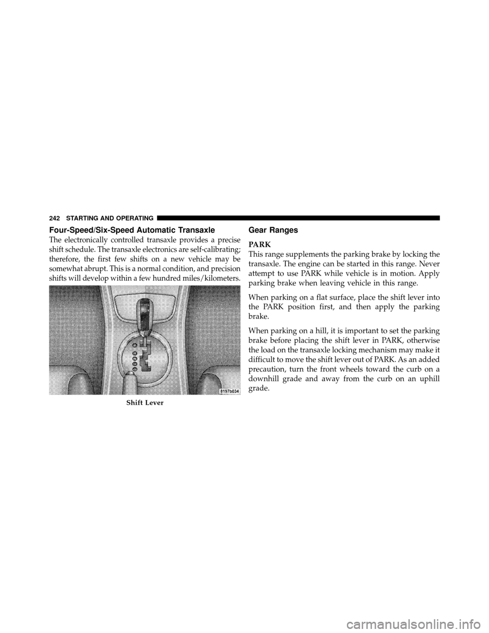
Four-Speed/Six-Speed Automatic Transaxle
The electronically controlled transaxle provides a precise
shift schedule. The transaxle electronics are self-calibrating;
therefore, the first few shifts on a new vehicle may be
somewhat abrupt. This is a normal condition, and precision
shifts will develop within a few hundred miles/kilometers.
Gear Ranges
PARK
This range supplements the parking brake by locking the
transaxle. The engine can be started in this range. Never
attempt to use PARK while vehicle is in motion. Apply
parking brake when leaving vehicle in this range.
When parking on a flat surface, place the shift lever into
the PARK position first, and then apply the parking
brake.
When parking on a hill, it is important to set the parking
brake before placing the shift lever in PARK, otherwise
the load on the transaxle locking mechanism may make it
difficult to move the shift lever out of PARK. As an added
precaution, turn the front wheels toward the curb on a
downhill grade and away from the curb on an uphill
grade.
Shift Lever
242 STARTING AND OPERATING