Page 94 of 444

Uconnect™ Phone — IF EQUIPPED
Uconnect™ Phone is a hands-free system that allows you
to use voice commands to dial a phone number stored
in your cellular phone. Press the Uconnect™ Phone
button
on the radio or steering wheel controls (if
equipped) and follow the instructions to pair the cellular
phone.
Refer to “Uconnect™ Phone” in the Uconnect™ User
Manual located on the DVD for further details.
VOICE COMMAND — IF EQUIPPED
Voice Command can be initiated by pressing the VR
button
located on the radio or steering wheel
controls (if equipped).
Refer to “Voice Command” in the Uconnect™ Phone
User Manual located on the DVD for further details.
SEATS
Seats are a primary part of the Occupant Restraint System
of the vehicle. They need to be used properly for safe
operation of the vehicle.
WARNING!
•DO NOT allow people to ride in any area of your
vehicle that is not equipped with seats and seat
belts. In a collision, people riding in these areas
are more likely to be seriously injured or killed.
•Be sure everyone in your vehicle is in a seat and
using a seat belt properly.
3
UNDERSTANDING THE FEATURES OF YOUR VEHICLE 93
Page 117 of 444

TILT/TELESCOPING STEERING COLUMN
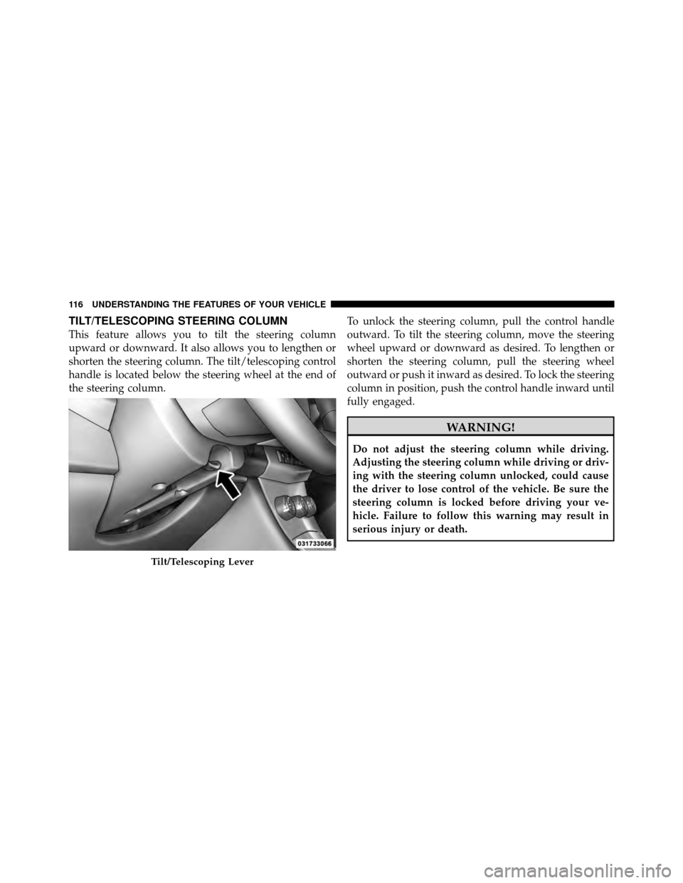
This feature allows you to tilt the steering column
upward or downward. It also allows you to lengthen or
shorten the steering column. The tilt/telescoping control
handle is located below the steering wheel at the end of
the steering column.To unlock the steering column, pull the control handle
outward. To tilt the steering column, move the steering
wheel upward or downward as desired. To lengthen or
shorten the steering column, pull the steering wheel
outward or push it inward as desired. To lock the steering
column in position, push the control handle inward until
fully engaged.
WARNING!
Do not adjust the steering column while driving.
Adjusting the steering column while driving or driv-
ing with the steering column unlocked, could cause
the driver to lose control of the vehicle. Be sure the
steering column is locked before driving your ve-
hicle. Failure to follow this warning may result in
serious injury or death.
Tilt/Telescoping Lever
116 UNDERSTANDING THE FEATURES OF YOUR VEHICLE
Page 118 of 444

ELECTRONIC SPEED CONTROL
When engaged, the Electronic Speed Control takes over
the accelerator operation at speeds greater than 25 mph
(40 km/h).
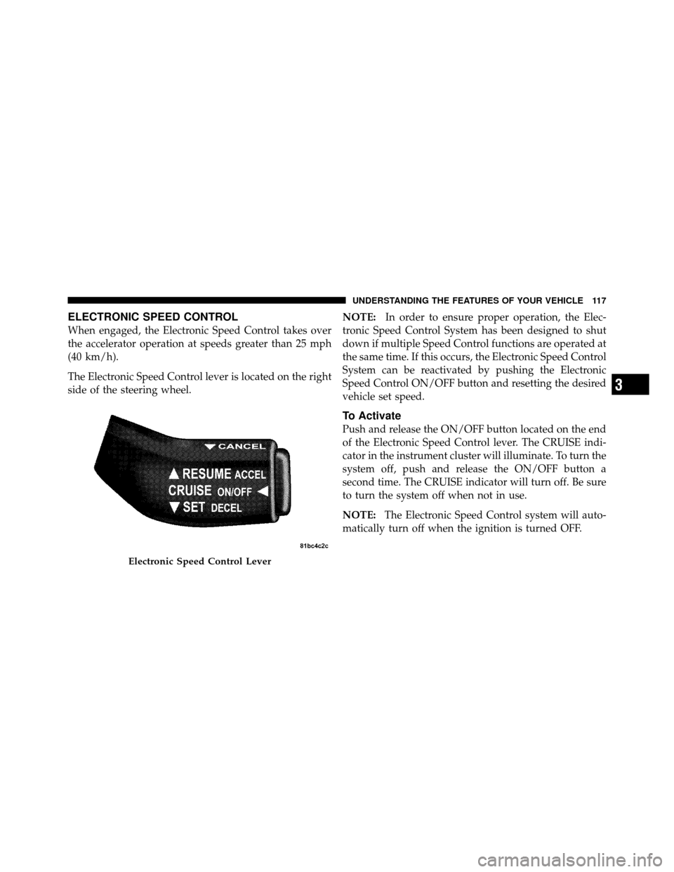
The Electronic Speed Control lever is located on the right
side of the steering wheel.NOTE:
In order to ensure proper operation, the Elec-
tronic Speed Control System has been designed to shut
down if multiple Speed Control functions are operated at
the same time. If this occurs, the Electronic Speed Control
System can be reactivated by pushing the Electronic
Speed Control ON/OFF button and resetting the desired
vehicle set speed.
To Activate
Push and release the ON/OFF button located on the end
of the Electronic Speed Control lever. The CRUISE indi-
cator in the instrument cluster will illuminate. To turn the
system off, push and release the ON/OFF button a
second time. The CRUISE indicator will turn off. Be sure
to turn the system off when not in use.
NOTE: The Electronic Speed Control system will auto-
matically turn off when the ignition is turned OFF.
Electronic Speed Control Lever
3
UNDERSTANDING THE FEATURES OF YOUR VEHICLE 117
Page 157 of 444

Your vehicle has also been equipped with a TPMS
malfunction indicator to indicate when the system is not
operating properly. The TPMS malfunction indicator is
combined with the low tire pressure telltale. When the
system detects a malfunction, the telltale will flash for
approximately one minute and then remain continuously
illuminated. This sequence will continue upon subse-
quent vehicle start-ups as long as the malfunction exists.
When the malfunction indicator is illuminated, the sys-
tem may not be able to detect or signal low tire pressure
as intended. TPMS malfunctions may occur for a variety
of reasons, including the installation of replacement or
alternate tires or wheels on the vehicle that prevent the
TPMS from functioning properly. Always check the
TPMS malfunction telltale after replacing one or more
tires or wheels on your vehicle, to ensure that the
replacement or alternate tires and wheels allow the TPMS
to continue to function properly.CAUTION!
The TPMS has been optimized for the original
equipment tires and wheels. TPMS pressures and
warning have been established for the tire size
equipped on your vehicle. Undesirable system opera-
tion or sensor damage may result when using re-
placement equipment that is not of the same size,
type, and/or style. Aftermarket wheels can cause
sensor damage. Do not use tire sealant from a can, or
balance beads if your vehicle is equipped with a
TPMS, as damage to the sensors may result.
26. Malfunction Indicator Light (MIL) The Malfunction Indicator Light (MIL) is part of
an onboard diagnostic system called OBD that
monitors emissions, engine, and automatic trans-
mission control systems. The light will illuminate when
the key is in the ON position before engine start. If the
156 UNDERSTANDING YOUR INSTRUMENT PANEL
Page 159 of 444

CAUTION!
Continuous driving with the Transmission Tempera-
ture Warning Light illuminated will eventually cause
severe transmission damage or transmission failure.
WARNING!
Continued operation with the Transmission Tem-
perature Warning Light illuminated could cause the
fluid to boil over, come in contact with hot engine or
exhaust components causing a fire that may result in
personal injury.
28. High Beam Indicator This light indicates that the headlights are on high
beam. Pull the turn signal lever toward the steer-
ing wheel to switch the headlights to low beam. 29. Electronic Vehicle Information Center (EVIC)
Display — If Equipped
This display shows the EVIC messages when the appro-
priate conditions exist. Refer to “Electronic Vehicle Infor-
mation Center (EVIC)” for further information.
ELECTRONIC VEHICLE INFORMATION CENTER
(EVIC) – IF EQUIPPED
The Electronic Vehicle Information Center (EVIC) fea-
tures a driver-interactive display that is located in the
instrument cluster.
158 UNDERSTANDING YOUR INSTRUMENT PANEL
Page 217 of 444
•A battery-powered infrared remote control snaps into
a molded compartment in the center console armrest
upper storage bin.
•Two wireless infrared headsets allow rear seat passen-
gers to listen to the same or individual audio sources.Audio/Video RCA Jacks (AUX Jacks)
on the rear of the center console enable
the monitor to display video directly
from a video camera, connect video
games for display on the screen, or
play music directly from an MP3
player.
1. Video in (yellow)
2. Left audio in (white)
3. Right audio in (red)
NOTE: Refer to the “Uconnect™ Multimedia” section of
Uconnect™ User Manual located on the DVD for further
details.REMOTE SOUND SYSTEM CONTROLS —
IF EQUIPPED
The remote sound system controls are located on the rear
surface of the steering wheel. The left and right controls
VES™ Remote Control
216 UNDERSTANDING YOUR INSTRUMENT PANEL
Page 218 of 444
are rocker-type switches with a pushbutton in the center
of each switch. Reach behind the steering wheel to access
the switches.Right-Hand Switch Functions
•
Press the top of the switch to increase the volume.
•Press the bottom of the switch to decrease the volume.
•Press the button in the center of the switch to change
modes (i.e., AM, FM, etc.).
Left-Hand Switch Functions for Radio Operation
•
Press the top of the switch to SEEK the next listenable
station up from the current setting.
•Press the bottom of the switch to SEEK the next
listenable station down from the current setting.
•Press the button in the center of the switch to tune to
the next preset that you have programmed.
Remote Sound System Controls(Back View Of Steering Wheel)
4
UNDERSTANDING YOUR INSTRUMENT PANEL 217
Page 238 of 444
▫Trailer And Tongue Weight ............. 312
▫ Towing Requirements ................. 313
▫ Towing Tips ........................ 317 �
Recreational Towing
(Behind Motorhome, Etc.) ................ 318
▫ Towing This Vehicle Behind Another Vehicle
(Flat Towing With All Four Wheels On The
Ground) ........................... 318
5
STARTING AND OPERATING 237