2010 CHRYSLER SEBRING CONVERTIBLE tow
[x] Cancel search: towPage 134 of 457

Headlights with Wipers (Available with Auto
Headlights Only)
When this feature is active, the headlights will turn on
approximately 10 seconds after the wipers are turned on
if the multifunction lever (on the left side of the steering
column) is placed in the AUTO position. In addition, the
headlights will turn off when the wipers are turned off if
they were turned on by this feature.
The Headlights with Wipers feature can be turned on or
off through the Electronic Vehicle Information Center
(EVIC) — if equipped. Refer to “Electronic Vehicle Infor-
mation Center (EVIC)/Personal Settings (Customer-
Programmable Features)” in “Understanding Your In-
strument Panel” for further information.
Windshield Washers
To use the washer, pull the windshield wiper/washer
control lever toward you and hold it for as long as
washer spray is desired.
If you activate the washer while the wiper control is in
the delay range, the wipers will operate in low-speed for
two wipe cycles after releasing the lever and then resume
the intermittent interval previously selected.
If you activate the washer while the wiper control is in
the off position, the wipers will operate for two wipe
cycles and then turn off.
3
UNDERSTANDING THE FEATURES OF YOUR VEHICLE 133
Page 137 of 457

WARNING!
Leaving the Electronic Speed Control on when not in
use is dangerous. You could accidentally set the
system or cause it to go faster than you want. You
could lose control and have an accident. Always
leave the system off when you are not using it.
To Set a Desired Speed
Turn the Electronic Speed Control ON. When the vehicle
reaches the speed desired, press down on the lever and
release SET DECEL. Release the accelerator and the
vehicle will operate at the selected speed.
NOTE:
•The vehicle must be traveling at least 25 mph
(40 km/h) for the Electronic Speed Control to set.
•The vehicle should be traveling at a steady speed and
on level ground before pressing the lever SET DECEL.
To Deactivate
A soft tap on the brake pedal, or pulling the Electronic
Speed Control lever toward you (CANCEL), or normal
brake pressure while slowing the vehicle will deactivate
the Electronic Speed Control without erasing the set
speed from memory. Pressing the ON/OFF button or
turning off the ignition erases the set speed from
memory.
To Resume Speed
If you deactivated the Electronic Speed Control without
erasing the set speed from memory and your vehicle
speed is above 20 mph (32 km/h) you can resume the
previous set speed. To do so, push the lever up and
release RESUME ACCEL, and then remove your foot
from the accelerator pedal.
To Vary the Speed Setting
When the Electronic Speed Control is set, you can in-
crease speed by pushing up and holding the RESUME
136 UNDERSTANDING THE FEATURES OF YOUR VEHICLE
Page 159 of 457

INSTRUMENT CLUSTER DESCRIPTIONS
1. Temperature Gauge
The temperature gauge shows engine coolant tempera-
ture. Any reading below the red area of the gauge shows
that the engine cooling system is operating properly. The
gauge pointer may show a higher than normal tempera-
ture when driving in hot weather, up mountain grades, in
heavy stop and go traffic, or when towing a trailer.
If the pointer rises to theH(red) mark, the instrument
cluster will sound a chime. Pull over and stop the vehicle.
Idle the vehicle with the air conditioner turned off until
the pointer drops back into the normal range. If the
pointer remains on the H(red) mark, turn the engine off
immediately and call for service.
There are steps that you can take to slow down an
impending overheat condition. If your air conditioning is
on, turn it off. The air conditioning system adds heat to
the engine cooling system and turning off the A/C removes this heat. You can also turn the Temperature
control to maximum heat, the Mode control to Floor and
the Fan control to High. This allows the heater core to act
as a supplement to the radiator and aids in removing heat
from the engine cooling system.
2. Fuel Door Reminder
This is a reminder that the Fuel Filler Door is
located on the left side of the vehicle.
3. Fuel Gauge
When the ignition switch is in the ON position, the
pointer will show the level of fuel remaining in the fuel
tank.
4. Speedometer
Indicates the vehicle speed in miles per hour (MPH) and
kilometers per hour (km/h).
158 UNDERSTANDING YOUR INSTRUMENT PANEL
Page 166 of 457

15. Cruise Indicator — If EquippedThis indicator shows that the Electronic Speed
Control System is ON.
16. Odometer/Trip Odometer Reset Button
Single Trip Odometer
Press and release this button to change the display from
odometer to trip odometer. The word “Trip” displays to
show that the odometer is in Trip Mode. Press and release
the button again to change the display back to the
odometer.
To reset the trip odometer, first set the display to Trip
Mode. Then push and hold the button (approximately
2 seconds) until the display resets to 0 miles (kilometers).
The odometer must be in Trip Mode to reset the trip
odometer. Dual Trip Odometer — If Equipped
Press and release this button to change the display from
odometer to “Trip A.” Press and release it a second time
to change the display to “Trip B.” Press and release it a
third time to change the display back to the odometer.
To reset the trip odometer, first display the trip mileage
that you want to reset, “Trip A” or “Trip B.” Then push
and hold the button (approximately 2 seconds) until the
display resets to 0 miles (kilometers). The odometer must
be in Trip Mode to reset the trip odometer.
17. Electronic Throttle Control (ETC) Indicator Light
This light informs you of a problem with the
Electronic Throttle Control (ETC) system. If a
problem is detected, the light will come on
while the engine is running. If the light remains
lit with the engine running, your vehicle will usually be
drivable and not need towing, however see your autho-
rized dealer for service as soon as possible.
4
UNDERSTANDING YOUR INSTRUMENT PANEL 165
Page 167 of 457

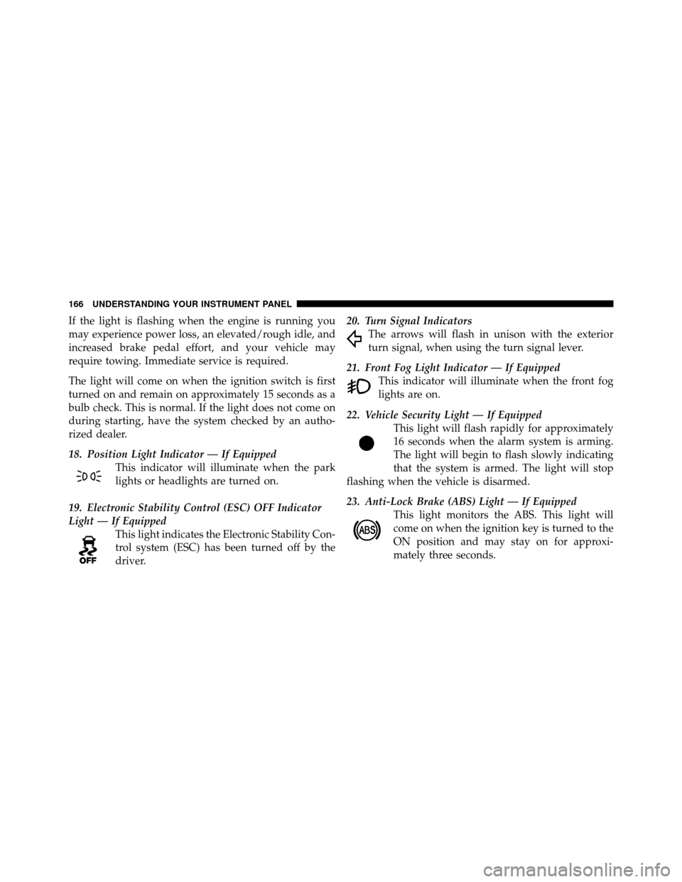
If the light is flashing when the engine is running you
may experience power loss, an elevated/rough idle, and
increased brake pedal effort, and your vehicle may
require towing. Immediate service is required.
The light will come on when the ignition switch is first
turned on and remain on approximately 15 seconds as a
bulb check. This is normal. If the light does not come on
during starting, have the system checked by an autho-
rized dealer.
18. Position Light Indicator — If EquippedThis indicator will illuminate when the park
lights or headlights are turned on.
19. Electronic Stability Control (ESC) OFF Indicator
Light — If Equipped This light indicates the Electronic Stability Con-
trol system (ESC) has been turned off by the
driver. 20. Turn Signal Indicators
The arrows will flash in unison with the exterior
turn signal, when using the turn signal lever.
21. Front Fog Light Indicator — If Equipped This indicator will illuminate when the front fog
lights are on.
22. Vehicle Security Light — If Equipped This light will flash rapidly for approximately
16 seconds when the alarm system is arming.
The light will begin to flash slowly indicating
that the system is armed. The light will stop
flashing when the vehicle is disarmed.
23. Anti-Lock Brake (ABS) Light — If Equipped This light monitors the ABS. This light will
come on when the ignition key is turned to the
ON position and may stay on for approxi-
mately three seconds.
166 UNDERSTANDING YOUR INSTRUMENT PANEL
Page 171 of 457

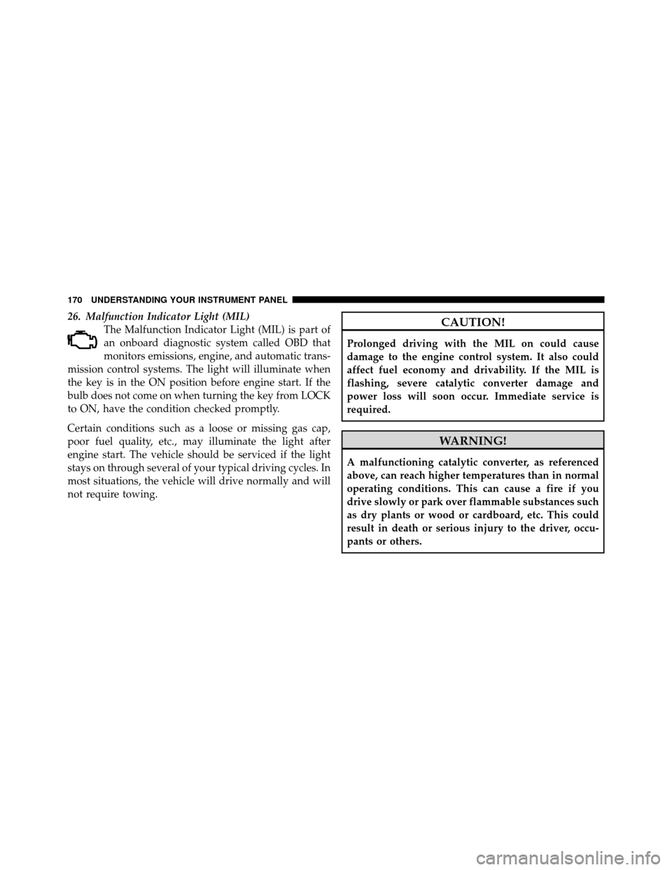
26. Malfunction Indicator Light (MIL)The Malfunction Indicator Light (MIL) is part of
an onboard diagnostic system called OBD that
monitors emissions, engine, and automatic trans-
mission control systems. The light will illuminate when
the key is in the ON position before engine start. If the
bulb does not come on when turning the key from LOCK
to ON, have the condition checked promptly.
Certain conditions such as a loose or missing gas cap,
poor fuel quality, etc., may illuminate the light after
engine start. The vehicle should be serviced if the light
stays on through several of your typical driving cycles. In
most situations, the vehicle will drive normally and will
not require towing.CAUTION!
Prolonged driving with the MIL on could cause
damage to the engine control system. It also could
affect fuel economy and drivability. If the MIL is
flashing, severe catalytic converter damage and
power loss will soon occur. Immediate service is
required.
WARNING!
A malfunctioning catalytic converter, as referenced
above, can reach higher temperatures than in normal
operating conditions. This can cause a fire if you
drive slowly or park over flammable substances such
as dry plants or wood or cardboard, etc. This could
result in death or serious injury to the driver, occu-
pants or others.
170 UNDERSTANDING YOUR INSTRUMENT PANEL
Page 172 of 457

27. Transmission Temperature Warning Light — If
EquippedThis light indicates that the transmission fluid
temperature is running hot. This may occur
with severe usage, such as trailer towing. If this
light turns on, safely pull over and stop the
vehicle. Then, shift the transmission into NEUTRAL and
run the engine at idle or faster until the light turns off.
CAUTION!
Continuous driving with the Transmission Tempera-
ture Warning Light illuminated will eventually cause
severe transmission damage or transmission failure.
WARNING!
Continued operation with the Transmission Tem-
perature Warning Light illuminated could cause the
fluid to boil over, come in contact with hot engine or
exhaust components causing a fire that may result in
personal injury.
28. High Beam Indicator This light indicates that the headlights are on high
beam. Pull the turn signal lever toward the steer-
ing wheel to switch the headlights to low beam.
29. Electronic Vehicle Information Center (EVIC)
Display — If Equipped
This display shows the EVIC messages when the appro-
priate conditions exist. Refer to “Electronic Vehicle Infor-
mation Center (EVIC)” for further information.
4
UNDERSTANDING YOUR INSTRUMENT PANEL 171
Page 233 of 457

Mode Control (Air Direction)
Rotate this control to choose from sev-
eral patterns of air distribution. You
can select either a primary mode as
identified by the symbols on the con-
trol, or a blend of two of these modes.
The closer the setting is to a particular
symbol, the more air distribution you
receive from that mode.
Panel Air is directed through the outlets in the instrument
panel. These outlets can be adjusted to direct airflow.
NOTE: The center instrument panel outlets can be
aimed so that they are directed toward the rear seat
passengers for maximum airflow to the rear.
Bi-Level Air is directed through the panel and floor outlets. NOTE:
For all settings except full cold or full hot, there
is a difference in temperature between the upper and
lower outlets. The warmer air flows to the floor outlets.
This feature gives improved comfort during sunny but
cool conditions.
Floor Air is directed through the floor outlets with a
small amount flowing through the defrost and side
window demist outlets.
Mix Air is directed through the floor, defrost, and side
window demist outlets. This setting works best in
cold or snowy conditions that require extra heat to
the windshield. This setting is good for maintaining
comfort while reducing moisture on the windshield.
232 UNDERSTANDING YOUR INSTRUMENT PANEL