Page 143 of 368
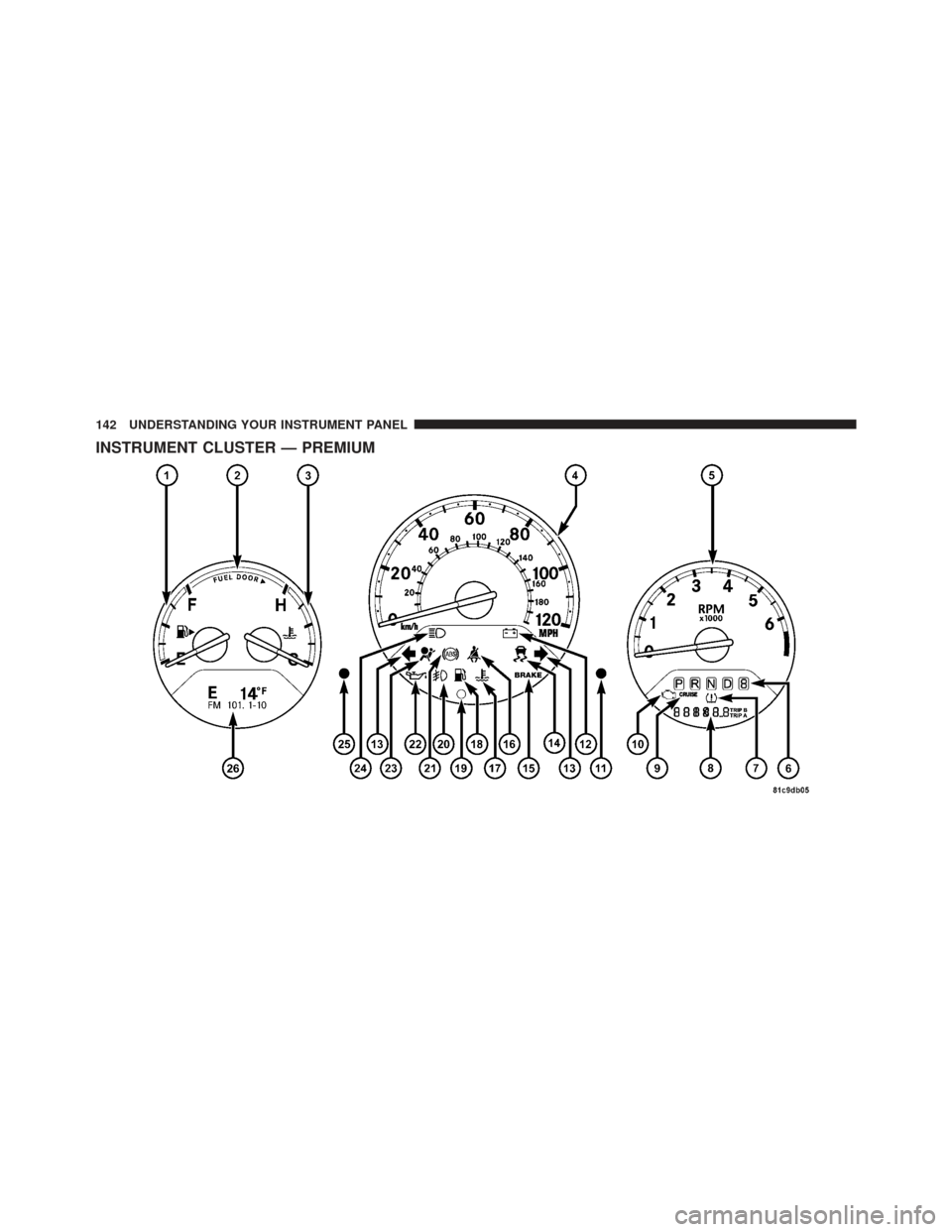
INSTRUMENT CLUSTER — PREMIUM
142 UNDERSTANDING YOUR INSTRUMENT PANEL
Page 144 of 368

INSTRUMENT CLUSTER DESCRIPTIONS
1. Fuel Gauge
When the ignition switch is in the ON position, the
pointer will show the level of fuel remaining in the fuel
tank.
2. Fuel Door Reminder
This is a reminder that the Fuel Filler Door is located on
the front passenger’s (right) side of the vehicle.
3. Temperature Gauge
The temperature gauge shows engine coolant tempera-
ture. Any reading within the normal range indicates that
the engine cooling system is operating satisfactorily.
The gauge pointer will likely indicate a higher tempera-
ture when driving in hot weather, up mountain grades,
or when towing a trailer. It should not be allowed to
exceed the upper limits of the normal operating range.
CAUTION!
Driving with a hot engine cooling system could
damage your vehicle. If temperature gauge reads “H”
pull over and stop the vehicle. Idle the vehicle with
the air conditioner turned off until the pointer drops
back into the normal range. If the pointer remains on
the “H” and you hear continuous chimes, turn the
engine off immediately, and call an authorized deal-
ership for service.
4
UNDERSTANDING YOUR INSTRUMENT PANEL 143
Page 145 of 368

WARNING!
A hot engine cooling system is dangerous. You or
others could be badly burned by steam or boiling
coolant. You may want to call an authorized dealer-
ship for service if your vehicle overheats. If you
decide to look under the hood yourself, see “Main-
taining Your Vehicle”. Follow the warnings under the
Cooling System Pressure Cap paragraph.
4. Speedometer
The Speedometer shows the vehicle speed in miles per
hour (mph) and/or kilometers per hour (km/h).
5. Tachometer
The white area of the scale shows the permissible engine
revolutions-per-minute (RPM x 1000) for each gear range.
Before reaching the red area, ease up on the accelerator to
prevent engine damage. 6. Shift Lever Indicator
The Shift Lever Indicator is self-contained within the
instrument cluster. It displays the gear position of the
automatic transmission.
NOTE:
You must apply the brakes before shifting from
PARK.
7. Tire Pressure Monitoring Telltale Light — If
Equipped Each tire, including the spare (if provided),
should be checked monthly, when cold and
inflated to the inflation pressure recommended
by the vehicle manufacturer on the vehicle
placard or tire inflation pressure label. (If your vehicle
has tires of a different size than the size indicated on the
vehicle placard or tire inflation pressure label, you should
determine the proper tire inflation pressure for those
tires.)
144 UNDERSTANDING YOUR INSTRUMENT PANEL
Page 156 of 368

COMPASS MINI-TRIP COMPUTER (CMTC) — IF
EQUIPPED
NOTE:The compass on your vehicle is self-calibrating,
eliminating the need to manually calibrate the compass.
The Compass Mini-Trip Computer features a driver-
interactive display (displays information on outside tem-
perature, compass direction, and trip information). The
display is located on the lower left part of the cluster
below the fuel and engine temperature gauge.
NOTE: The system will display the last known outside
temperature when starting the vehicle and may need to
be driven several minutes before the updated tempera-
ture is displayed. Engine temperature can also affect the
displayed temperature, therefore temperature readings
are not updated when the vehicle is not moving.
Compass Mini-Trip Computer Reset Button
CMTC Reset Button — Secondary Reset Button
Press the left Compass/Temperature RESET button to
scroll through sub-menus (i.e., Trip Functions: AVG Fuel
Economy, DTE Elapsed Time, and Units (US or Metric).
When the appropriate conditions exist, the following
messages will display in the window below the fuel and
engine temperature gauge:
E ........ Eight-point compass headings are displayed
(N, S, E, W, NE, NW, SE, SW)
14°F ............ T emperature (Fahrenheit or Celsius)
AV G .......... Average Fuel Economy (US or Metric)
DTE ....................... Distance to Empty
ET ............................ Elapsed Time
NOTE: Temperature and Average Fuel Economy can be
changed from U.S. or Metric. by pressing and holding the
(left) secondary pushbutton.
4
UNDERSTANDING YOUR INSTRUMENT PANEL 155
Page 159 of 368

3. Release the RESET button, then press and hold again
(approximately 10 seconds), until the direction is dis-
played with the CAL indicator on continuously in the
display.
4. To complete the compass calibration, drive the vehicle
in one or more complete 360 degree circles, under 5 mph
(8 km/h) in an area free from power lines and large
metallic objects, until the CAL indicator turns off. The
compass will now function normally.
Odometer Display
When the appropriate conditions exist, the following
odometer messages will display:
CRUISE...................... Cruise Activated
gASCAP ....................... Fuel Cap Fault
noFUSE .......................... Fuse FaultThese messages can be manually turned off by pressing
the right reset button (on the instrument cluster).
Trip Odometer (ODO)
This display shows the distance traveled since the last
reset. Press and release the right button (on the instru-
ment cluster) to switch from odometer, to trip A or trip B.
Press and hold the right button while the odometer/trip
odometer is displayed, to reset.
Trip A
Shows the total distance traveled for trip A since the last
reset.
Trip B
Shows the total distance traveled for trip B since the last
reset.
158 UNDERSTANDING YOUR INSTRUMENT PANEL
Page 160 of 368
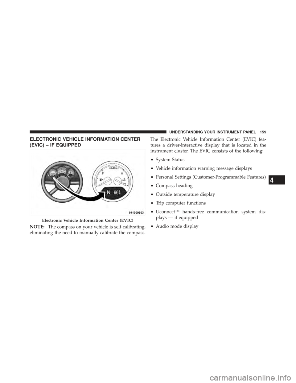
ELECTRONIC VEHICLE INFORMATION CENTER
(EVIC) – IF EQUIPPED
NOTE:The compass on your vehicle is self-calibrating,
eliminating the need to manually calibrate the compass. The Electronic Vehicle Information Center (EVIC) fea-
tures a driver-interactive display that is located in the
instrument cluster. The EVIC consists of the following:
•System Status
•Vehicle information warning message displays
•Personal Settings (Customer-Programmable Features)
•Compass heading
•Outside temperature display
•Trip computer functions
•Uconnect™ hands-free communication system dis-
plays — if equipped
•Audio mode display
Electronic Vehicle Information Center (EVIC)
4
UNDERSTANDING YOUR INSTRUMENT PANEL 159
Page 201 of 368

LOW — 1st
This range should be used for maximum engine braking
when descending steep grades. In this range, up shifts
will occur only to prevent engine over speed while down
shifts from second to first gear will occur as early as
possible.
AUTOSTICK�— IF EQUIPPED
AutoStick�is a driver-interactive transmission that offers
manual gear-shifting capability to provide you with more
control. AutoStick� allows you to maximize engine brak-
ing, eliminate undesirable upshifts and downshifts, and
improve overall vehicle performance. This system can
also provide you with more control during passing, city
driving, cold slippery conditions, mountain driving,
trailer towing, and many other situations.
Operation
The AutoStick� position is just below the OVERDRIVE
position and is identified by the word “AutoStick”. When you move the shift lever into the AutoStick
�position, it
can be moved from side to side. Moving the lever to the
left (-) triggers a downshift and to the right (+) an upshift.
The gear position will be shown in the gear display,
located in the instrument cluster.
NOTE:
•In AutoStick� mode, the transmission will only shift
up and down when the driver manually moves the
shift lever right (D+) or left (D-).
•An UPSHIFT message will appear in the Electronic
Vehicle Information Center (EVIC) portion of the in-
strument cluster. This message appears in order to
alert the driver to upshift to the next gear. The
UPSHIFT message will display while operating the
vehicle at higher engine revolutions per minute
(RPM).
200 STARTING AND OPERATING
Page 208 of 368
If necessary, add fluid to restore to the proper indicated
level. With a clean cloth, wipe any spilled fluid from all
surfaces. Refer to “Fluids, Lubricants, and Genuine
Parts” in “Maintaining Your Vehicle” for further
information.
PARKING BRAKE
Before leaving the vehicle, make sure that the parking
brake is fully applied. Also, be certain to leave the
transmission in PARK.
The parking brake lever is located in the center console.
To apply the parking brake, pull the lever up as firmly as
possible. To release the parking brake, pull the lever up
slightly, press the center button, then lower the lever
completely.When the parking brake is applied with the ignition
switch ON, the “Brake Warning Light” in the instrument
cluster will illuminate.
Parking Brake
5
STARTING AND OPERATING 207