Page 222 of 538

10. Electronic Stability Program (ESP) / Brake Assist
System (BAS) Malfunction Indicator LightThe yellow Electronic Stability Program (ESP)
/ Brake Assist System (BAS) Malfunction Indi-
cator Light will turn on when the key in the
ignition switch is placed in the RUN position.
The light should go out with the engine running. The
system will turn this light on continuously while the
engine is running if it detects a malfunction in either the
ESP, the BAS or both.WARNING!
If a warning light remains on the system may not be
working and you will not have the benefit of ESP or
BAS. Under certain driving conditions, where ESP or
BAS would be beneficial, you - if you have not
adjusted your driving speeds and stopping in or to
account for the lack of the feature, may be in acci-
dent.
11. Airbag Warning Light This light will turn on for six to eight seconds
as a bulb check when the ignition switch is first
placed in the RUN position. If the light is either
not on during starting, or stays on, or turns on
while driving, then have the system inspected at an
authorized dealer as soon as possible. Refer to “Occupant
Restraints” in “Things To Know Before Starting Your
Vehicle” for further information.
4
UNDERSTANDING YOUR INSTRUMENT PANEL 221
Page 223 of 538

12. Brake Warning LightThis light monitors various brake functions,
including brake fluid level and parking brake
application. If the brake light turns on, it may
indicate that the parking brake is applied, that
the brake fluid level is low, or that there is a problem with
the anti-lock brake system reservoir.
If the light remains on when the parking brake has been
disengaged, and the fluid level is at the full mark on the
master cylinder reservoir, it indicates a possible brake
hydraulic system malfunction. In this case, the light will
remain on until the condition has been corrected.
The dual brake system provides a reserve braking capac-
ity in the event of a failure to a portion of the hydraulic
system. A leak in either half of the dual brake system is
indicated by the Brake Warning Light which will turn on
when the brake fluid level in the master cylinder has
dropped below a specified level. The light will remain on until the cause is corrected.
NOTE:
The light may flash momentarily during sharp
cornering maneuvers which change fluid level condi-
tions. The vehicle should have service performed, and
the brake fluid level checked.
If brake failure is indicated, immediate repair is neces-
sary.
WARNING!
Driving a vehicle with the brake light on is danger-
ous. Part of the brake system may have failed. It will
take longer to stop the vehicle. You could have an
accident. Have the vehicle checked immediately.
222 UNDERSTANDING YOUR INSTRUMENT PANEL
Page 224 of 538

Vehicles equipped with the Anti-Lock Brake System
(ABS), are also equipped with Electronic Brake Force
Distribution (EBD). In the event of an EBD failure, the
Brake Warning Light will turn on along with the ABS
Light. Immediate repair to the ABS system is required.
Operation of the Brake Warning Light can be checked by
turning the ignition switch from the OFF position to the
RUN position. The light should illuminate for approxi-
mately two seconds. The light should then turn off unless
the parking brake is applied or a brake fault is detected.
If the light does not illuminate, have the light inspected
by an authorized dealer.
The light also will turn on when the parking brake is
applied with the ignition switch in the RUN position.
NOTE:This light shows only that the parking brake is
applied. It does not show the degree of brake application. 13. Electronic Stability Program (ESP) / Traction
Control System (TCS) Indicator Light — If Equipped
If this indicator light flashes during accelera-
tion, ease up on the accelerator and apply as
little throttle as possible. Adapt your speed and
driving to the prevailing road conditions, and
do not switch off the Electronic Stability Program (ESP).
14. Temperature Gauge
The temperature gauge shows engine coolant tempera-
ture. Any reading within the normal range indicates that
the engine cooling system is operating satisfactorily.
The gauge pointer will likely indicate a higher tempera-
ture when driving in hot weather, up mountain grades,
or when towing a trailer. It should not be allowed to
exceed the upper limits of the normal operating range.
4
UNDERSTANDING YOUR INSTRUMENT PANEL 223
Page 225 of 538

CAUTION!
Driving with a hot engine cooling system could
damage your vehicle. If the temperature gauge reads
“H,” pull over and stop the vehicle. Idle the vehicle
with the air conditioner turned off until the pointer
drops back into the normal range. If the pointer
remains on the “H,” and you hear continuous chimes,
turn the engine OFF immediately and call for service.
WARNING!
A hot engine cooling system is dangerous. You or
others could be badly burned by steam or boiling
coolant. You may want to call a service center if your
vehicle overheats. If you decide to look under the
hood yourself, refer to “Maintaining Your Vehicle”
and follow the warnings under the Cooling System
Pressure Cap paragraph.15. Trip Odometer Button
Trip Odometer Button — Base Cluster
The word
�TRIP�will appear when this button is pressed.
Push in and hold the button for two seconds when the
trip odometer displays to reset it to 0 miles (km). A
second press of the button will display the outside
temperature in the odometer.
Trip Odometer Button — Premium Cluster
Press this button to change the display from odometer to
either of two trip odometer settings. The letter “A” or “B”
will appear when in the trip odometer mode. Push in and
hold the button for two seconds to reset the trip odometer
to 0 miles (km). The odometer must be in TRIP mode to
reset it.
224 UNDERSTANDING YOUR INSTRUMENT PANEL
Page 293 of 538

CD/DVD DISC MAINTENANCE
To keep a CD/DVD in good condition, take the following
precautions:
1. Handle the disc by its edge; avoid touching the
surface.
2. If the disc is stained, clean the surface with a soft cloth,
wiping from center to edge.
3. Do not apply paper or tape to the disc; avoid scratch-
ing the disc.
4. Do not use solvents such as benzene, thinner, cleaners,
or anti-static sprays.
5. Store the disc in its case after playing.
6. Do not expose the disc to direct sunlight.
7. Do not store the disc where temperatures may become
too high.NOTE:
If you experience difficulty in playing a particu-
lar disc, it may be damaged (i.e., scratched, reflective
coating removed, a hair, moisture or dew on the disc)
oversized, or have protection encoding. Try a known
good disc before considering disc player service.
RADIO OPERATION AND CELLULAR PHONES
Under certain conditions, the cellular phone being on in
your vehicle can cause erratic or noisy performance from
your radio. This condition may be lessened or eliminated
by relocating the cellular phone antenna. This condition
is not harmful to the radio. If your radio performance
does not satisfactorily “clear” by the repositioning of the
antenna, it is recommended that the radio volume be
turned down or off during cellular phone operation.
CLIMATE CONTROLS
The air conditioning and heating system is designed to
make you comfortable in all types of weather.
292 UNDERSTANDING YOUR INSTRUMENT PANEL
Page 294 of 538
Manual Air Conditioning and Heating SystemBlower Control
The rotary knob on the left controls the
blower. The control has an OFF posi-
tion and four speed settings.The
blower will remain on until the con-
trol is turned to the OFF position or
the ignition is turned OFF.
NOTE: For vehicles equipped with Remote Start, the
climate controls will not function during Remote Start
operation if the blower control is left in the “O” (Off)
position.
Manual Temperature Controls
4
UNDERSTANDING YOUR INSTRUMENT PANEL 293
Page 296 of 538

•Bi-LevelAir flows through the outlets located in the instru-
ment panel and through the outlets located on the
floor. Air flows through the registers in the back of the
center console to the rear seat passengers. These registers
can be closed to partially block airflow.
•Panel Air flows through the outlets located in the instru-
ment panel. Air flows through the registers in the
back of the center console to the rear seat passengers.
These registers can be closed to block airflow.
•Recirculation Control The mode control knob also controls the recir-
culation feature. You can choose Bi-Level Re-
circulation air outlets, Panel Recirculation air
outlets, or a mix or both while in this mode.
Normally, air enters from outside the vehicle. However,
when in Recirculation mode air inside the vehicle is re-used. Use this mode to cool the inside of the vehicle
rapidly. The Recirculation mode can also be used to
temporarily block out outside odors, smoke, and dust.
Air Conditioning Control
Press this button to turn the air conditioning on
and off. When the air conditioning is turned
on, cool dehumidified air will flow through the
outlets selected with the mode control. Press
this button a second time to turn off the air conditioning.
An indicator in the button will illuminate when compres-
sor operation is selected.
4
UNDERSTANDING YOUR INSTRUMENT PANEL 295
Page 297 of 538

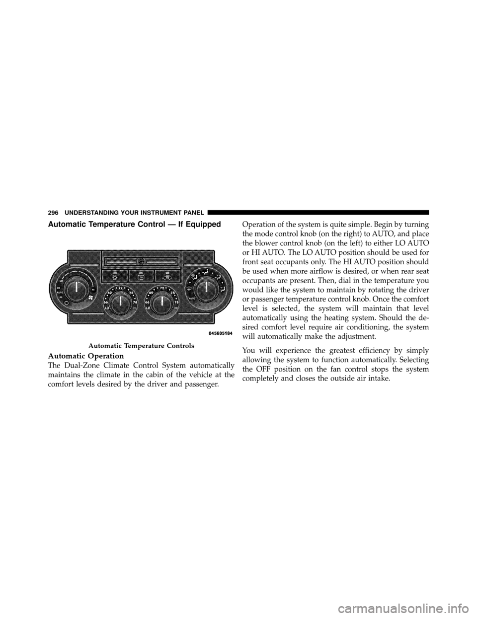
Automatic Temperature Control — If Equipped
Automatic Operation
The Dual-Zone Climate Control System automatically
maintains the climate in the cabin of the vehicle at the
comfort levels desired by the driver and passenger.Operation of the system is quite simple. Begin by turning
the mode control knob (on the right) to AUTO, and place
the blower control knob (on the left) to either LO AUTO
or HI AUTO. The LO AUTO position should be used for
front seat occupants only. The HI AUTO position should
be used when more airflow is desired, or when rear seat
occupants are present. Then, dial in the temperature you
would like the system to maintain by rotating the driver
or passenger temperature control knob. Once the comfort
level is selected, the system will maintain that level
automatically using the heating system. Should the de-
sired comfort level require air conditioning, the system
will automatically make the adjustment.
You will experience the greatest efficiency by simply
allowing the system to function automatically. Selecting
the OFF position on the fan control stops the system
completely and closes the outside air intake.
Automatic Temperature Controls
296 UNDERSTANDING YOUR INSTRUMENT PANEL