2010 CHEVROLET SUBURBAN wheel
[x] Cancel search: wheelPage 479 of 608
.For all 6.0L 1500 series and all 6.2L non‐all wheel
drive 1500 series luxury model applications, the
proper level is from 0.6 inch to 1.6 inches (15 mm
to 40 mm) below the bottom of the filler plug hole,
located on the rear axle. Add only enough fluid to
reach the proper level.
.The proper fill level for the 2500 series is from 0 to
1/2 inch (0 to 13 mm) below the bottom of the filler
plug hole, located at the front of the axle. Add only
enough fluid to reach the proper level.
Four-Wheel Drive
Lubricant checks in this section also apply to these
vehicles. There are two additional systems that need
lubrication.
Transfer Case
When to Check Lubricant
It is not necessary to regularly check transfer case fluid
unless you suspect there is a leak, or you hear an
unusual noise. A fluid loss could indicate a problem.
Have it inspected and repaired.
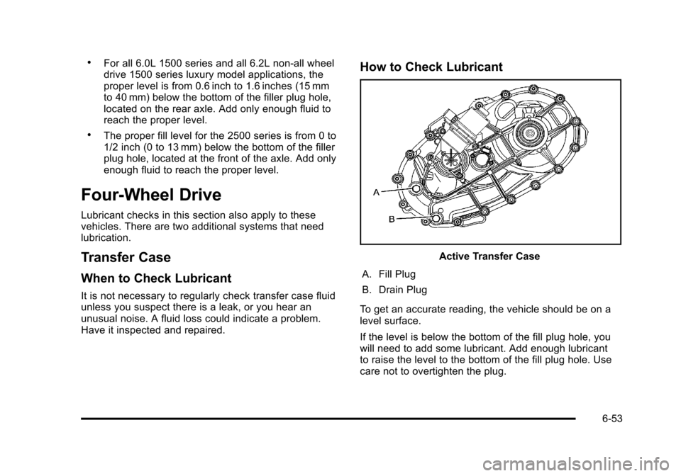
How to Check Lubricant
Active Transfer Case
A. Fill Plug
B. Drain Plug
To get an accurate reading, the vehicle should be on a
level surface.
If the level is below the bottom of the fill plug hole, you
will need to add some lubricant. Add enough lubricant
to raise the level to the bottom of the fill plug hole. Use
care not to overtighten the plug.
6-53
Page 493 of 608
(F) Tire Ply Material:The type of cord and
number of plies in the sidewall and under the
tread.
(G) Single Tire Maximum Load
:Maximum load
that can be carried and the maximum pressure
needed to support that load when used as a
single. For information on recommended tire
pressure see Inflation - Tire Pressure
on page 6‑72
andLoading the Vehicleon page 5‑29.
Tire Size
The following examples show the different parts of
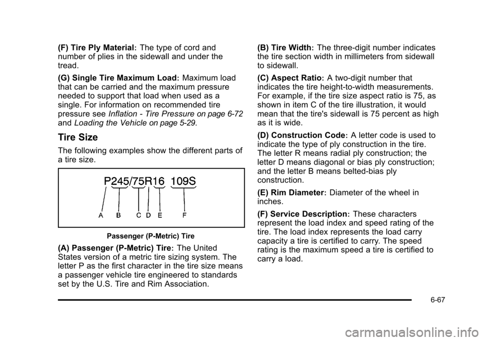
a tire size.
Passenger (P‐Metric) Tire
(A) Passenger (P‐Metric) Tire:The United
States version of a metric tire sizing system. The
letter P as the first character in the tire size means
a passenger vehicle tire engineered to standards
set by the U.S. Tire and Rim Association. (B) Tire Width
:The three‐digit number indicates
the tire section width in millimeters from sidewall
to sidewall.
(C) Aspect Ratio
:A two‐digit number that
indicates the tire height‐to‐width measurements.
For example, if the tire size aspect ratio is 75, as
shown in item C of the tire illustration, it would
mean that the tire's sidewall is 75 percent as high
as it is wide.
(D) Construction Code
:A letter code is used to
indicate the type of ply construction in the tire.
The letter R means radial ply construction; the
letter D means diagonal or bias ply construction;
and the letter B means belted‐bias ply
construction.
(E) Rim Diameter
:Diameter of the wheel in
inches.
(F) Service Description
:These characters
represent the load index and speed rating of the
tire. The load index represents the load carry
capacity a tire is certified to carry. The speed
rating is the maximum speed a tire is certified to
carry a load.
6-67
Page 494 of 608
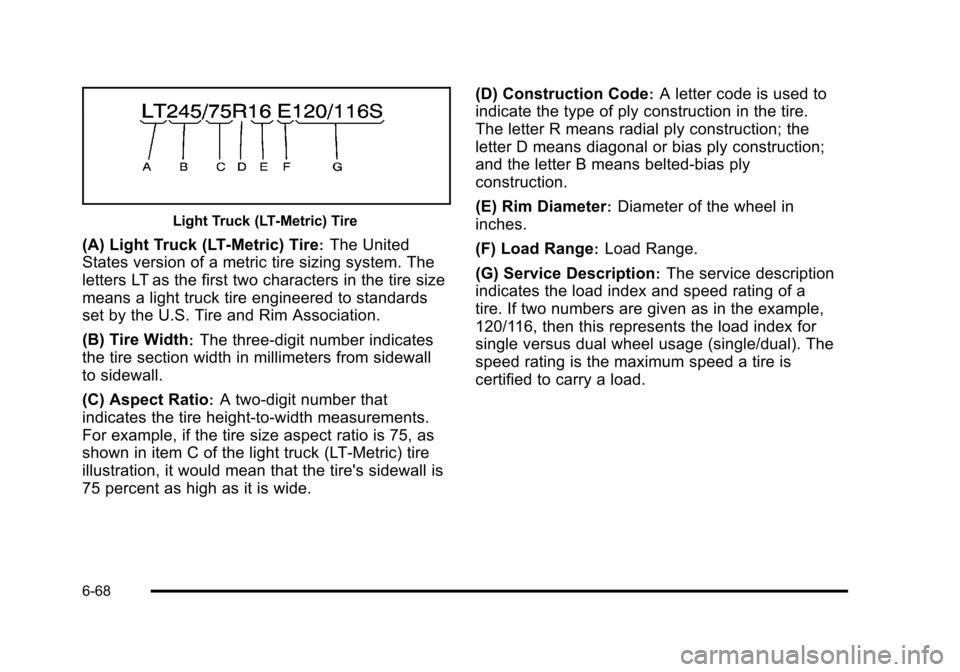
Light Truck (LT‐Metric) Tire
(A) Light Truck (LT‐Metric) Tire:The United
States version of a metric tire sizing system. The
letters LT as the first two characters in the tire size
means a light truck tire engineered to standards
set by the U.S. Tire and Rim Association.
(B) Tire Width
:The three‐digit number indicates
the tire section width in millimeters from sidewall
to sidewall.
(C) Aspect Ratio
:A two‐digit number that
indicates the tire height‐to‐width measurements.
For example, if the tire size aspect ratio is 75, as
shown in item C of the light truck (LT‐Metric) tire
illustration, it would mean that the tire's sidewall is
75 percent as high as it is wide. (D) Construction Code
:A letter code is used to
indicate the type of ply construction in the tire.
The letter R means radial ply construction; the
letter D means diagonal or bias ply construction;
and the letter B means belted‐bias ply
construction.
(E) Rim Diameter
:Diameter of the wheel in
inches.
(F) Load Range
:Load Range.
(G) Service Description
:The service description
indicates the load index and speed rating of a
tire. If two numbers are given as in the example,
120/116, then this represents the load index for
single versus dual wheel usage (single/dual). The
speed rating is the maximum speed a tire is
certified to carry a load.
6-68
Page 500 of 608
Please note that the TPMS is not a substitute for proper
tire maintenance, and it is the driver's responsibility to
maintain correct tire pressure, even if under‐inflation
has not reached the level to trigger illumination of the
TPMS low tire pressure telltale.
Your vehicle has also been equipped with a TPMS
malfunction indicator to indicate when the system is
not operating properly. The TPMS malfunction indicator
is combined with the low tire pressure telltale. When
the system detects a malfunction, the telltale will
flash for approximately one minute and then remain
continuously illuminated. This sequence will continue
upon subsequent vehicle start‐ups as long as the
malfunction exists.
When the malfunction indicator is illuminated, the
system may not be able to detect or signal low tire
pressure as intended. TPMS malfunctions may occur
for a variety of reasons, including the installation of
replacement or alternate tires or wheels on the vehicle
that prevent the TPMS from functioning properly.
Always check the TPMS malfunction telltale after
replacing one or more tires or wheels on your vehicle
to ensure that the replacement or alternate tires and
wheels allow the TPMS to continue to function properly.
SeeTire Pressure Monitor Operation
on page 6‑74for
additional information.
Federal Communications Commission
(FCC) and Industry Canada
See Radio Frequency Statementon page 8‑19for information regarding Part 15 of the Federal
Communications Commission (FCC) Rules and
RSS-210/211 of Industry Canada.
Tire Pressure Monitor Operation
If your vehicle is a Two‐mode Hybrid, see the
Two‐mode Hybrid manual for more information.
This vehicle may have a Tire Pressure Monitor System
(TPMS). The TPMS is designed to warn the driver when
a low tire pressure condition exists. TPMS sensors are
mounted onto each tire and wheel assembly, excluding
the spare tire and wheel assembly. The TPMS sensors
monitor the air pressure in the vehicle's tires and
transmit the tire pressure readings to a receiver located
in the vehicle.
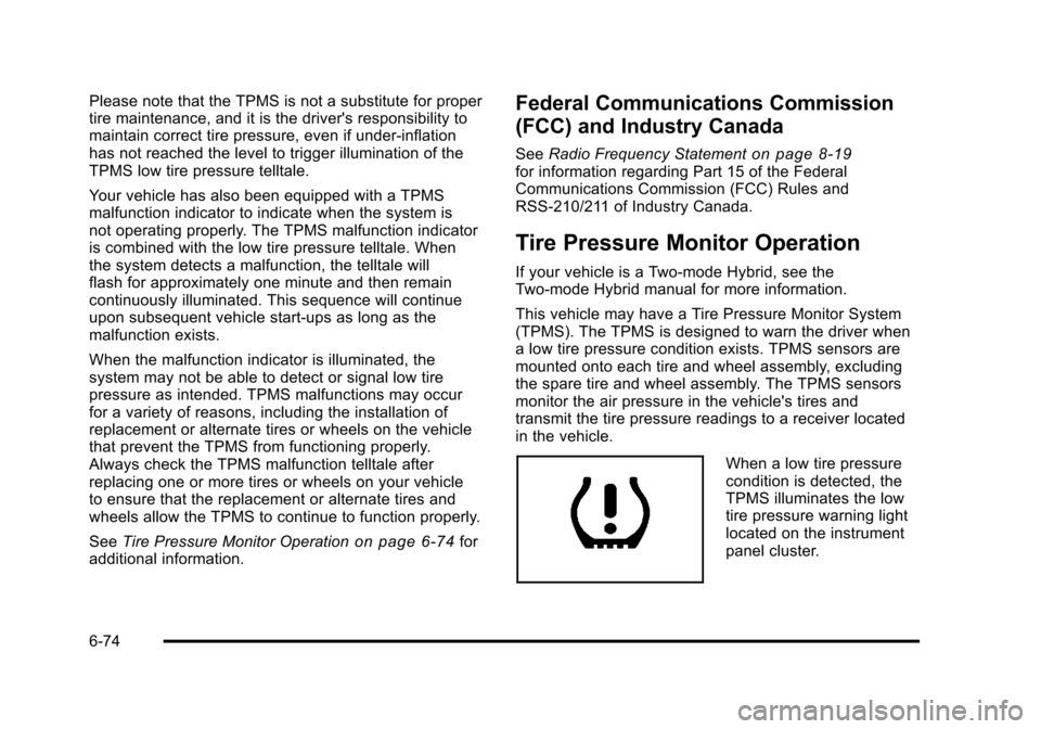
When a low tire pressure
condition is detected, the
TPMS illuminates the low
tire pressure warning light
located on the instrument
panel cluster.
6-74
Page 502 of 608
.One or more TPMS sensors are missing or
damaged. The DIC message and the TPMS
malfunction light should go off when the TPMS
sensors are installed and the sensor matching
process is performed successfully. See your dealer
for service.
.Replacement tires or wheels do not match your
vehicle's original equipment tires or wheels. Tires
and wheels other than those recommended for
your vehicle could prevent the TPMS from
functioning properly. SeeBuying New Tires
on
page 6‑80.
.Operating electronic devices or being near facilities
using radio wave frequencies similar to the TPMS
could cause the TPMS sensors to malfunction.
If the TPMS is not functioning it cannot detect or signal
a low tire condition. See your dealer for service if the
TPMS malfunction light and DIC message comes on
and stays on.
TPMS Sensor Matching Process
Each TPMS sensor has a unique identification code.
Any time you rotate your vehicle's tires or replace one
or more of the TPMS sensors, the identification codes
will need to be matched to the new tire/wheel position.
The sensors are matched to the tire/wheel positions in
the following order: driver side front tire, passenger side
front tire, passenger side rear tire, and driver side rear
tire using a TPMS diagnostic tool. See your dealer for
service.
The TPMS sensors can also be matched to each
tire/wheel position by increasing or decreasing the tire's
air pressure. If increasing the tire's air pressure, do not
exceed the maximum inflation pressure indicated on the
tire's sidewall.
To decrease air-pressure out of a tire you can use the
pointed end of the valve cap, a pencil-style air pressure
gauge, or a key.
You have two minutes to match the first tire/wheel
position, and five minutes overall to match all
four tire/wheel positions. If it takes longer than
two minutes, to match the first tire and wheel, or
more than five minutes to match all four tire and wheel
positions the matching process stops and you need to
start over.
6-76
Page 503 of 608

The TPMS sensor matching process is outlined below:1. Set the parking brake.
2. Turn the ignition switch to ON/RUN with the engine off.
3. Press
QandKon the Remote Keyless
Entry (RKE) transmitter at the same time for
approximately five seconds. The horn sounds twice
to signal the receiver is in relearn mode and TIRE
LEARNING ACTIVE message displays on the DIC
screen.
4. Start with the driver side front tire.
5. Remove the valve cap from the valve cap stem. Activate the TPMS sensor by increasing or
decreasing the tire's air pressure for five seconds,
or until a horn chirp sounds. The horn chirp, which
may take up to 30 seconds to sound, confirms that
the sensor identification code has been matched to
this tire and wheel position. 6. Proceed to the passenger side front tire, and
repeat the procedure in Step 5.
7. Proceed to the passenger side rear tire, and repeat the procedure in Step 5.
8. Proceed to the driver side rear tire, and repeat the procedure in Step 5. The horn sounds two times to
indicate the sensor identification code has been
matched to the driver side rear tire, and the TPMS
sensor matching process is no longer active. The
TIRE LEARNING ACTIVE message on the DIC
display screen goes off.
9. Turn the ignition switch to LOCK/OFF.
10. Set all four tires to the recommended air pressure level as indicated on the Tire and Loading
Information label.
11. Put the valve caps back on the valve stems.
6-77
Page 504 of 608
Tire Inspection and Rotation
We recommend that you regularly inspect your
vehicle's tires, including the spare tire, for signs of
wear or damage. SeeWhen It Is Time for New
Tires
on page 6‑79for more information.
Tires should be rotated every 5,000 to 8,000 miles
(8 000 to 13 000 km). See Scheduled Maintenance
on page 7‑3.
The purpose of a regular tire rotation is to achieve
a uniform wear for all tires on the vehicle. This will
ensure that your vehicle continues to perform
most like it did when the tires were new.
Any time you notice unusual wear, rotate your
tires as soon as possible and check wheel
alignment. Also check for damaged tires or
wheels. See When It Is Time for New Tires
on
page 6‑79
and Wheel Replacementon page 6‑84.
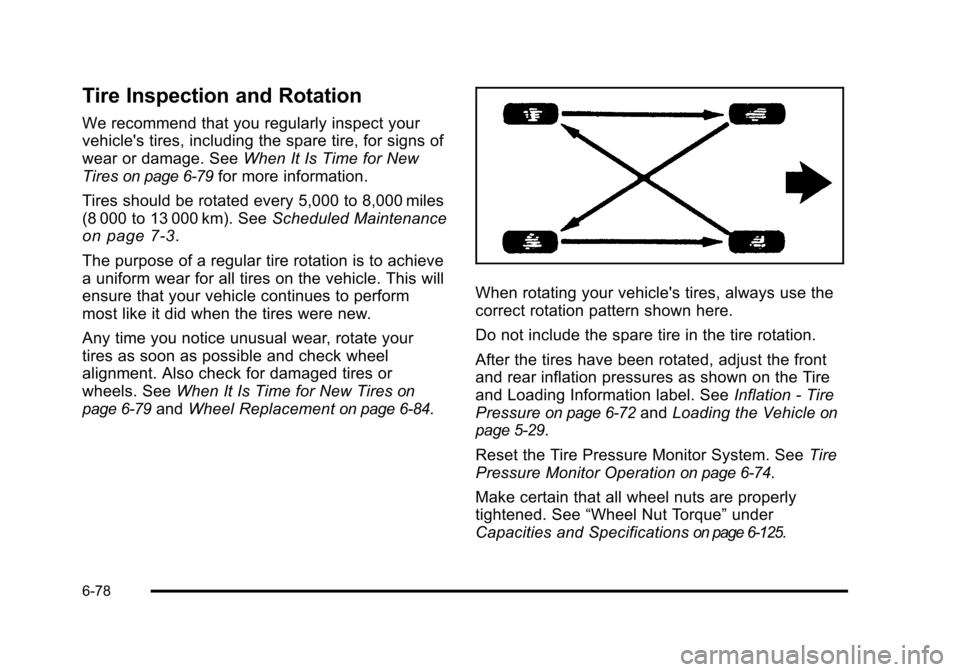
When rotating your vehicle's tires, always use the
correct rotation pattern shown here.
Do not include the spare tire in the tire rotation.
After the tires have been rotated, adjust the front
and rear inflation pressures as shown on the Tire
and Loading Information label. See Inflation - Tire
Pressure
on page 6‑72and Loading the Vehicleon
page 5‑29
.
Reset the Tire Pressure Monitor System. See Tire
Pressure Monitor Operation
on page 6‑74.
Make certain that all wheel nuts are properly
tightened. See “Wheel Nut Torque” under
Capacities and Specifications
on page 6‑125.
6-78
Page 505 of 608
{WARNING:
Rust or dirt on a wheel, or on the parts to
which it is fastened, can make wheel nuts
become loose after time. The wheel could
come off and cause an accident. When you
change a wheel, remove any rust or dirt from
places where the wheel attaches to the
vehicle. In an emergency, you can use a
cloth or a paper towel to do this; but be
sure to use a scraper or wire brush later,
if needed, to get all the rust or dirt off.
SeeChanging a Flat Tire
on page 6‑88.
Make sure the spare tire is stored securely. Push,
pull, and then try to rotate or turn the tire. If it
moves, tighten the cable. See Storing a Flat or
Spare Tire and Tools
on page 6‑104.
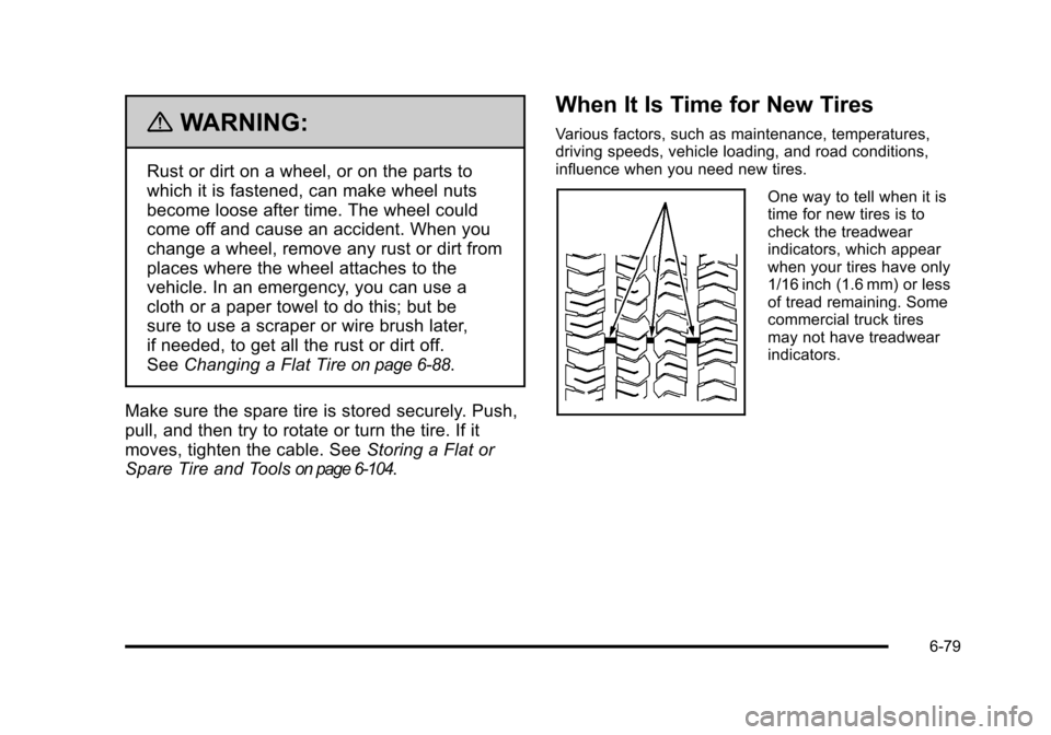
When It Is Time for New Tires
Various factors, such as maintenance, temperatures,
driving speeds, vehicle loading, and road conditions,
influence when you need new tires.
One way to tell when it is
time for new tires is to
check the treadwear
indicators, which appear
when your tires have only
1/16 inch (1.6 mm) or less
of tread remaining. Some
commercial truck tires
may not have treadwear
indicators.
6-79