Page 473 of 626
3. Install the dipstick by pushing it back in all the way,wait three seconds, and then pull it back out again.
4. Check both sides of the dipstick and read the lower level. Repeat the check procedure to verify the
reading.
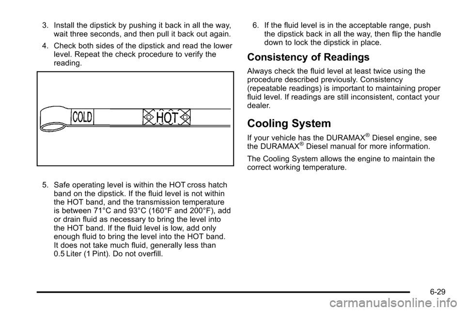
5. Safe operating level is within the HOT cross hatchband on the dipstick. If the fluid level is not within
the HOT band, and the transmission temperature
is between 71°C and 93°C (160°F and 200°F), add
or drain fluid as necessary to bring the level into
the HOT band. If the fluid level is low, add only
enough fluid to bring the level into the HOT band.
It does not take much fluid, generally less than
0.5 Liter (1 Pint). Do not overfill. 6. If the fluid level is in the acceptable range, push
the dipstick back in all the way, then flip the handle
down to lock the dipstick in place.
Consistency of Readings
Always check the fluid level at least twice using the
procedure described previously. Consistency
(repeatable readings) is important to maintaining proper
fluid level. If readings are still inconsistent, contact your
dealer.
Cooling System
If your vehicle has the DURAMAX®Diesel engine, see
the DURAMAX®Diesel manual for more information.
The Cooling System allows the engine to maintain the
correct working temperature.
6-29
Page 481 of 626
Notice:After driving in the overheated engine
protection operating mode, to avoid engine damage,
allow the engine to cool before attempting any
repair. The engine oil will be severely degraded.
Repair the cause of coolant loss, change the oil and
reset the oil life system. See Engine Oil
on
page 6‑18.
Engine Fan Noise
If the vehicle has a clutched engine cooling fan, when
the clutch is engaged, the fan spins faster to provide
more air to cool the engine. In most everyday driving
conditions, the fan is spinning slower and the clutch is
not fully engaged. This improves fuel economy and
reduces fan noise. Under heavy vehicle loading, trailer
towing, and/or high outside temperatures, the fan speed
increases as the clutch more fully engages, so you may
hear an increase in fan noise. This is normal and should
not be mistaken as the transmission slipping or making
extra shifts. It is merely the cooling system functioning
properly. The fan will slow down when additional cooling
is not required and the clutch disengages.
You may also hear this fan noise when you start the
engine. It will go away as the fan clutch partially
disengages.
If the vehicle has electric cooling fans, you may hear
the fans spinning at low speed during most everyday
driving. The fans may turn off if no cooling is required. Under heavy vehicle loading, trailer towing, and/or high
outside temperatures, or if you are operating the air
conditioning system, the fans may change to high
speed and you may hear an increase in fan noise. This
is normal and indicates that the cooling system is
functioning properly. The fans will change to low speed
when additional cooling is no longer required.
Power Steering Fluid
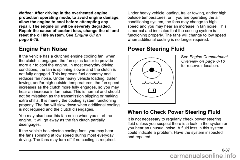
See
Engine Compartment
Overviewon page 6‑16for reservoir location.
When to Check Power Steering Fluid
It is not necessary to regularly check power steering
fluid unless you suspect there is a leak in the system or
you hear an unusual noise. A fluid loss in this system
could indicate a problem. Have the system inspected
and repaired.
6-37
Page 489 of 626
To avoid the possibility of the vehicles rolling, set
the parking brake firmly on both vehicles involved
in the jump start procedure. Put the automatic
transmission in P (Park) or a manual transmission
in Neutral before setting the parking brake. If you
have a four-wheel-drive vehicle, be sure the
transfer case is in a drive gear, not in Neutral.
Notice: If you leave the radio or other accessories
on during the jump starting procedure, they could
be damaged. The repairs would not be covered by
the warranty. Always turn off the radio and other
accessories when jump starting the vehicle.
4. Turn off the ignition on both vehicles. Unplug unnecessary accessories plugged into the
cigarette lighter or the accessory power outlets.
Turn off the radio and all the lamps that are not
needed. This will avoid sparks and help save both
batteries. And it could save the radio!
5. Open the hood on the other vehicle and locate the positive (+) and negative (−) terminal locations on
that vehicle.
The positive (+) terminal, is located under a red
plastic cover at the positive battery post. To
uncover the positive (+) terminal, open the red
plastic cover.
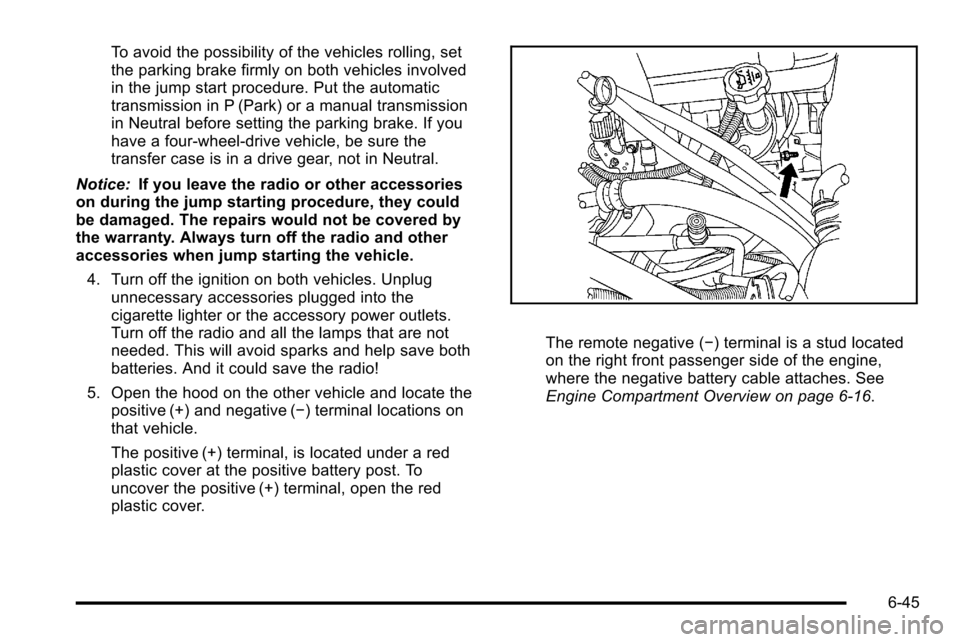
The remote negative (−) terminal is a stud located
on the right front passenger side of the engine,
where the negative battery cable attaches. See
Engine Compartment Overview on page 6‑16.
6-45
Page 514 of 626
Tire Terminology and Definitions
Air Pressure:The amount of air inside the tire
pressing outward on each square inch of the tire.
Air pressure is expressed in pounds per square
inch (psi) or kilopascal (kPa).
Accessory Weight
:This means the combined
weight of optional accessories. Some examples of
optional accessories are, automatic transmission,
power steering, power brakes, power windows,
power seats, and air conditioning.
Aspect Ratio
:The relationship of a tire's height to
its width.
Belt
:A rubber coated layer of cords that is
located between the plies and the tread. Cords
may be made from steel or other reinforcing
materials.
Bead
:The tire bead contains steel wires wrapped
by steel cords that hold the tire onto the rim.
Bias Ply Tire
:A pneumatic tire in which the plies
are laid at alternate angles less than 90 degrees
to the centerline of the tread. Cold Tire Pressure
:The amount of air pressure
in a tire, measured in pounds per square inch (psi)
or kilopascals (kPa) before a tire has built up heat
from driving. See Inflation - Tire Pressure
on
page 6‑73
.
Curb Weight
:The weight of a motor vehicle with
standard and optional equipment including the
maximum capacity of fuel, oil, and coolant, but
without passengers and cargo.
DOT Markings
:A code molded into the sidewall
of a tire signifying that the tire is in compliance
with the U.S. Department of Transportation (DOT)
motor vehicle safety standards. The DOT code
includes the Tire Identification Number (TIN), an
alphanumeric designator which can also identify
the tire manufacturer, production plant, brand, and
date of production.
GVWR
:Gross Vehicle Weight Rating. See
Loading the Vehicle
on page 5‑29.
GAWR FRT
:Gross Axle Weight Rating for the
front axle. See Loading the Vehicle
on page 5‑29.
GAWR RR
:Gross Axle Weight Rating for the rear
axle. See Loading the Vehicle
on page 5‑29.
6-70
Page 534 of 626
A rear blowout, particularly on a curve, acts much like a
skid and may require the same correction you would
use in a skid. In any rear blowout remove your foot from
the accelerator pedal. Get the vehicle under control by
steering the way you want the vehicle to go. It may be
very bumpy and noisy, but you can still steer. Gently
brake to a stop, well off the road if possible.
{WARNING:
Lifting a vehicle and getting under it to do
maintenance or repairs is dangerous without the
appropriate safety equipment and training. If a
jack is provided with the vehicle, it is designed
only for changing a flat tire. If it is used for
anything else, you or others could be badly
injured or killed if the vehicle slips off the jack. If a
jack is provided with the vehicle, only use it for
changing a flat tire.
If a tire goes flat, the next part shows how to use the
jacking equipment to change a flat tire safely.
Changing a Flat Tire
If a tire goes flat, avoid further tire and wheel damage
by driving slowly to a level place. Turn on the hazard
warning flashers. See Hazard Warning Flashers
on
page 4‑3.
{WARNING:
Changing a tire can be dangerous. The vehicle
can slip off the jack and roll over or fall on you or
other people. You and they could be badly injured
or even killed. Find a level place to change your
tire. To help prevent the vehicle from moving:
1. Set the parking brake firmly.
2. Put an automatic transmission shift lever in P (Park), or shift a manual transmission to
1 (First) or R (Reverse).
(Continued)
6-90
Page 567 of 626
FusesUsage
5Engine Control Module, Throttle
Control
6 Trailer Brake Controller
7 Front Washer
8 Oxygen Sensor
9 Antilock Brakes System 2
10 Trailer Back-up Lamps 11 Driver Side Low-Beam Headlamp
12 Engine Control Module (Battery)
13 Fuel Injectors, Ignition Coils
(Right Side)
14 Transmission Control Module
(Battery)
15 Vehicle Back-up Lamps
16 Passenger Side Low-Beam Headlamp
17 Air Conditioning Compressor
18 Oxygen Sensors
19 Transmission Controls (Ignition)
20 Fuel Pump
21 Fuel System Control Module
22 Not Used
Fuses Usage
23 Not Used
24Fuel Injectors, Ignition Coils
(Left Side)
25 Trailer Park Lamps
26 Driver Side Park Lamps
27 Passenger Side Park Lamps
28 Fog Lamps
29 Horn
30 Passenger Side High-Beam
Headlamp
31 Daytime Running Lamps (DRL)
32 Driver Side High-Beam Headlamp
33 Daytime Running Lights 2
34 Sunroof
35 Key Ignition System, Theft Deterrent
System
36 Windshield Wiper
37 SEO B2 Upfitter Usage (Battery)
38 Electric Adjustable Pedals
6-123
Page 571 of 626
ApplicationCapacities
English Metric
Fuel Tank
1500 Series Standard and Short Box 26.0 gal 98.0 L
1500 Series Long Box 34.0 gal 128.7 L
2500 Series Standard Box 26.0 gal 98.0 L
2500 Series and 3500 Series Long Box 34.0 gal 128.7 L
3500 Series Chassis Cab 50.0 gal 189.0 L
3500 Chassis Cab –Front Tank 27.0 gal 102.0 L
3500 Chassis Cab –Rear Tank (if equipped) 23.0 gal 87.0 L
Transmission Fluid (Pan Removal and Filter Replacement) Auto 4-Speed Transmission 4L60-E Electronic Transmission 5.0 qt 4.7 L
Auto 6-Speed Transmission 6L80-E 6.0 qt 5.7 L
Auto 6-Speed Transmission 6L90-E 6.3 qt 6.0 L
Auto 6-Speed Transmission Allison 7.4 qt 7.0 L
Transfer Case Fluid 1.6 qt 1.5 L
Wheel Nut Torque 140 ft lb 190 Y
All capacities are approximate. When adding, be sure to fill to the approximate level, as recommended in this manual.
Recheck fluid level after filling.
6-127
Page 572 of 626
Engine Specifications
EngineVIN CodeTransmission Spark Plug Gap
4.3L V6 (LU3) XAutomatic 0.060 in (1.52 mm)
4.8L V8 (L20) AAutomatic 0.040 in (1.02 mm)
5.3L V8 Flexible Fuel with Active
Fuel Management™ (Iron
Block) (LMG) 0
Automatic 0.040 in (1.02 mm)
5.3L V8 Flexible Fuel with Active
Fuel Management™(Aluminum
Block) (LC9) 3
Automatic 0.040 in (1.02 mm)
6.0L V8 (Iron Block) (L96 or LY6) G or K Automatic0.040 in (1.02 mm)
6.2L V8 Flexible Fuel (Aluminum
Block) (L9H) 2
Automatic 0.040 in (1.02 mm)
6-128