Page 482 of 626

How to Check Power Steering Fluid
To check the power steering fluid:1. Turn the key off and let the engine compartment cool down.
2. Wipe the cap and the top of the reservoir clean.
3. Unscrew the cap and wipe the dipstick with a clean rag.
4. Replace the cap and completely tighten it.
5. Remove the cap again and look at the fluid level on the dipstick.
The level should be at the FULL COLD mark.
If necessary, add only enough fluid to bring the level up
to the mark.
What to Use
To determine what kind of fluid to use, see
Recommended Fluids and Lubricantson page 7‑13.
Always use the proper fluid.
Notice: Use of the incorrect fluid may damage the
vehicle and the damages may not be covered by the
vehicle's warranty. Always use the correct fluid
listed in Recommended Fluids and Lubricants
on
page 7‑13.
Windshield Washer Fluid
What to Use
When windshield washer fluid needs to be added, be
sure to read the manufacturer's instructions before use.
Use a fluid that has sufficient protection against freezing
in an area where the temperature may fall below
freezing.
Adding Washer Fluid
The vehicle has a low washer fluid message in the DIC
that comes on when the washer fluid is low. The
message is displayed for 15 seconds at the start of
each ignition cycle. When the WASHER FLUID LOW
ADD FLUID message displays, you will need to add
washer fluid to the windshield washer fluid reservoir.
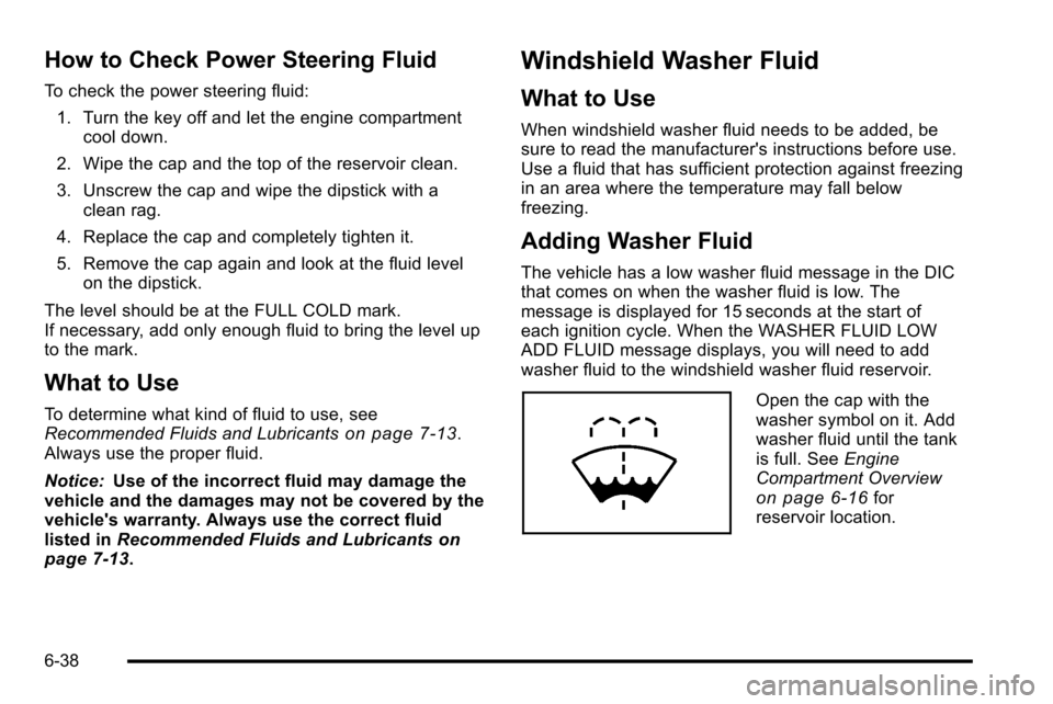
Open the cap with the
washer symbol on it. Add
washer fluid until the tank
is full. See Engine
Compartment Overview
on page 6‑16for
reservoir location.
6-38
Page 522 of 626

.One or more TPMS sensors are missing or
damaged. The DIC message and the TPMS
malfunction light should go off when the TPMS
sensors are installed and the sensor matching
process is performed successfully. See your dealer
for service.
.Replacement tires or wheels do not match your
vehicle's original equipment tires or wheels. Tires
and wheels other than those recommended for
your vehicle could prevent the TPMS from
functioning properly. SeeBuying New Tires
on
page 6‑83.
.Operating electronic devices or being near facilities
using radio wave frequencies similar to the TPMS
could cause the TPMS sensors to malfunction.
If the TPMS is not functioning it cannot detect or signal
a low tire condition. See your dealer for service if the
TPMS malfunction light and DIC message comes on
and stays on.
TPMS Sensor Matching Process
Each TPMS sensor has a unique identification code.
Any time you rotate your vehicle's tires or replace one
or more of the TPMS sensors, the identification codes
will need to be matched to the new tire/wheel position.
The sensors are matched to the tire/wheel positions in
the following order: driver side front tire, passenger side
front tire, passenger side rear tire, and driver side rear
tire using a TPMS diagnostic tool. See your dealer for
service.
The TPMS sensors can also be matched to each tire/
wheel position by increasing or decreasing the tire's air
pressure. If increasing the tire's air pressure, do not
exceed the maximum inflation pressure indicated on the
tire's sidewall.
To decrease air-pressure out of a tire you can use the
pointed end of the valve cap, a pencil-style air pressure
gauge, or a key.
You have two minutes to match the first tire/wheel
position, and five minutes overall to match all four tire/
wheel positions. If it takes longer than two minutes, to
match the first tire and wheel, or more than five minutes
to match all four tire and wheel positions the matching
process stops and you need to start over.
6-78
Page 523 of 626

The TPMS sensor matching process is outlined below:1. Set the parking brake.
2. Turn the ignition switch to ON/RUN with the engine off.
3. Press the Remote Keyless Entry (RKE) transmitter's LOCK and UNLOCK buttons at the
same time for approximately five seconds. The
horn sounds twice to signal the receiver is in
relearn mode and TIRE LEARNING ACTIVE
message displays on the DIC screen.
If your vehicle does not have RKE, press the
Driver Information Center (DIC) vehicle information
button until the PRESS
VTO RELEARN TIRE
POSITIONS message displays. The horn sounds
twice to signal the receiver is in relearn mode and
TIRE LEARNING ACTIVE message displays on
the DIC screen.
If your vehicle does not have RKE or DIC buttons,
press the trip odometer reset stem located on the
instrument panel cluster until the PRESS
VTO
RELEARN TIRE POSITIONS message displays.
The horn sounds twice to signal the receiver is in
relearn mode and TIRE LEARNING ACTIVE
message displays on the DIC screen.
4. Start with the driver side front tire. 5. Remove the valve cap from the valve cap stem.
Activate the TPMS sensor by increasing or
decreasing the tire's air pressure for five seconds,
or until a horn chirp sounds. The horn chirp, which
may take up to 30 seconds to sound, confirms that
the sensor identification code has been matched to
this tire and wheel position.
6. Proceed to the passenger side front tire, and repeat the procedure in Step 5.
7. Proceed to the passenger side rear tire, and repeat the procedure in Step 5.
8. Proceed to the driver side rear tire, and repeat the procedure in Step 5. The horn sounds two times to
indicate the sensor identification code has been
matched to the driver side rear tire, and that the
TPMS sensor matching process is no longer
active. The TIRE LEARNING ACTIVE message on
the DIC display screen goes off.
9. Turn the ignition switch to LOCK/OFF.
10. Set all four tires to the recommended air pressure level as indicated on the Tire and Loading
Information label.
11. Put the valve caps back on the valve stems.
6-79
Page 538 of 626
A. Spare Tire (ValveStem Pointed Down)
B. Hoist Assembly
C. Hoist Cable
D. Tire/Wheel Retainer E. Hoist Shaft F. Hoist End of
Extension Tool
G. Hoist Shaft Access Hole H. Wheel Wrench I. Jack Handle Extensions
J. Spare Tire Lock (If equipped) 1. Open the spare tire lock cover on the bumper and
use the ignition key to remove the spare tire
lock (J). To remove the spare tire lock, insert the
ignition key turn and pull straight out.
2. Assemble the wheel wrench (H) and the two jack
handle extensions (I) as shown.
6-94
Page 564 of 626
FusesUsage
9Passenger Door Module, Driver
Unlock
10 Power Door Lock 2 (Unlock Feature) 11 Power Door Lock 2 (Lock Feature)
12 Stoplamps, Center-High Mounted
Stoplamp
13 Rear Climate Controls
14 Power Mirror
15 Body Control Module (BCM)
16 Accessory Power Outlets
17 Interior Lamps
18 Power Door Lock 1 (Unlock Feature)
19 Rear Seat Entertainment
20 Ultrasonic Rear Parking Assist, Power
Liftgate
21 Power Door Lock 1 (Lock Feature)
Fuses Usage
22 Driver Information Center (DIC)
23 Rear Wiper
24 Cooled Seats
25Driver Seat Module, Remote Keyless
Entry System
26 Driver Power Door Lock (Unlock
Feature)
Circuit Breaker
Usage
LT DRDriver Side Power Window Circuit
Breaker
Harness
Connector Usage
LT DR Driver Door Harness Connection
BODY Harness Connector
BODY Harness Connector
6-120
Page 567 of 626
FusesUsage
5Engine Control Module, Throttle
Control
6 Trailer Brake Controller
7 Front Washer
8 Oxygen Sensor
9 Antilock Brakes System 2
10 Trailer Back-up Lamps 11 Driver Side Low-Beam Headlamp
12 Engine Control Module (Battery)
13 Fuel Injectors, Ignition Coils
(Right Side)
14 Transmission Control Module
(Battery)
15 Vehicle Back-up Lamps
16 Passenger Side Low-Beam Headlamp
17 Air Conditioning Compressor
18 Oxygen Sensors
19 Transmission Controls (Ignition)
20 Fuel Pump
21 Fuel System Control Module
22 Not Used
Fuses Usage
23 Not Used
24Fuel Injectors, Ignition Coils
(Left Side)
25 Trailer Park Lamps
26 Driver Side Park Lamps
27 Passenger Side Park Lamps
28 Fog Lamps
29 Horn
30 Passenger Side High-Beam
Headlamp
31 Daytime Running Lamps (DRL)
32 Driver Side High-Beam Headlamp
33 Daytime Running Lights 2
34 Sunroof
35 Key Ignition System, Theft Deterrent
System
36 Windshield Wiper
37 SEO B2 Upfitter Usage (Battery)
38 Electric Adjustable Pedals
6-123
Page 577 of 626

.Body hinges and latches, key lock cylinders,
folding seat hardware, and tailgate hinges, linkage,
and handle pivot points lubrication. See
Recommended Fluids and Lubricants
on
page 7‑13. More frequent lubrication may be
required when vehicle is exposed to a corrosive
environment. Applying silicone grease on
weatherstrips with a clean cloth makes them last
longer, seal better, and not stick or squeak.
.Restraint system component check. See Checking
the Restraint Systems on page 2‑94.
.Automatic transmission fluid level check and
adding fluid, if needed. See Automatic
Transmission Fluid (4-Speed Transmission)
on
page 6‑23or Automatic Transmission Fluid
(6-Speed Transmission) on page 6‑26.
.Four‐wheel drive vehicles: Transfer case fluid level
check and adding fluid, if needed.
.Engine air cleaner filter inspection. See Engine Air
Cleaner/Filter on page 6‑21.
.Vehicles with diesel engine or GVWR above
4 536 kg (10,000 lbs) only: Shields inspection for
damage or looseness. Adjust or replace as
required. This is a Noise Emission Control Service.
Applicable to vehicles sold in the United States
and recommended for vehicles sold in Canada.
Additional Required Services
At the First 160 km/100 Miles,
1 600 km/1,000 Miles, and
10 000 km/6,000 Miles
.For vehicles with dual wheels: Check dual wheel
nut torque. For proper torque, see Capacities and
Specifications on page 6‑126.
At Each Fuel Stop
.Engine oil level check. See Engine Oilon
page 6‑18.
.Engine coolant level check. See Engine Coolanton page 6‑31.
.Windshield washer fluid level check. See
Windshield Washer Fluid on page 6‑38.
Once a Month
.Tire inflation check. SeeInflation - Tire Pressureon page 6‑73.
.Tire wear inspection. See Tire Inspection and
Rotation on page 6‑80.
7-5
Page 584 of 626

Ignition Transmission Lock Check
While parked, and with the parking brake set, try to turn
the ignition to LOCK/OFF in each shift lever position.
.The ignition should turn to LOCK/OFF only when
the shift lever is in P (Park).
.The ignition key should come out only in
LOCK/OFF.
Contact your dealer if service is required.
Parking Brake and Automatic
Transmission P (Park) Mechanism
Check
{WARNING:
When you are doing this check, the vehicle could
begin to move. You or others could be injured and
property could be damaged. Make sure there is
room in front of the vehicle in case it begins to
roll. Be ready to apply the regular brake at once
should the vehicle begin to move. Park on a fairly steep hill, with the vehicle facing
downhill. Keeping your foot on the regular brake, set the
parking brake.
.To check the parking brake's holding ability: With
the engine running and the transmission in
N (Neutral), slowly remove foot pressure from the
regular brake pedal. Do this until the vehicle is held
by the parking brake only.
.To check the P (Park) mechanism's holding ability:
With the engine running, shift to P (Park). Then
release the parking brake followed by the regular
brake.
Contact your dealer if service is required.
7-12