2010 CHEVROLET HHR run flat
[x] Cancel search: run flatPage 201 of 480

Tire Pressure Light
For vehicles with a tire
pressure monitoring
system, this light comes
on briefly when the engine
is started. It provides
information about tire
pressures and the Tire
Pressure Monitoring
System.
When the Light is On Steady
This indicates that one or more of the tires is
significantly underinflated.
A tire pressure message in the Driver Information
Center (DIC), can accompany the light. SeeDriver
Information Center (DIC)
on page 4‑46for more
information. Stop and check the tires as soon as it is
safe to do so. If underinflated, inflate to the proper
pressure. See Inflation - Tire Pressure
on page 6‑63for more information.
When the Light Flashes First and Then is
On Steady
This indicates that there may be a problem with the Tire
Pressure Monitor System. The light flashes for about a
minute and stays on steady for the remainder of the
ignition cycle. This sequence repeats with every ignition
cycle. SeeTire Pressure Monitor Operation
on
page 6‑65for more information.
Malfunction Indicator Lamp
Check Engine Light
A computer system called OBD II (On-Board
Diagnostics-Second Generation) monitors operation
of the fuel, ignition, and emission control systems.
It ensures that emissions are at acceptable levels for
the life of the vehicle, helping to produce a cleaner
environment.
This light should come
on when the ignition is
on, but the engine is not
running, as a check to
show it is working. If it
does not, have the vehicle
serviced by your dealer/
retailer.
4-35
Page 282 of 480
Hill and Mountain Roads
Driving on steep hills or through mountains is different
than driving on flat or rolling terrain. Tips for driving in
these conditions include:
.Keep the vehicle serviced and in good shape.
.Check all fluid levels and brakes, tires, cooling
system, and transmission.
.Going down steep or long hills, shift to a
lower gear.
{WARNING:
If you do not shift down, the brakes could get so
hot that they would not work well. You would then
have poor braking or even none going down a hill.
You could crash. Shift down to let the engine
assist the brakes on a steep downhill slope.
{WARNING:
Coasting downhill in N (Neutral) or with the
ignition off is dangerous. The brakes will have to
do all the work of slowing down and they could
get so hot that they would not work well. You
would then have poor braking or even none going
down a hill. You could crash. Always have the
engine running and the vehicle in gear when
going downhill.
.Stay in your own lane. Do not swing wide or cut
across the center of the road. Drive at speeds that
let you stay in your own lane.
.Top of hills: Be alert—something could be in your
lane (stalled car, accident).
.Pay attention to special road signs (falling rocks
area, winding roads, long grades, passing or
no-passing zones) and take appropriate action.
5-20
Page 370 of 480
TPMS Sensor Matching Process
Each TPMS sensor has a unique identification code.
Any time you replace one or more of the TPMS sensors
or rotate the vehicle's tires, the identification codes
need to be matched to the new tire/wheel location. The
sensors are matched, to the tire/wheel locations, in the
following order: driver side front tire, passenger side
front tire, passenger side rear tire, and driver side rear
tire using a TPMS diagnostic tool. See your dealer/
retailer for service.
The TPMS sensors can also be matched to each
tire/wheel position by increasing or decreasing the tire's
air pressure. When increasing the tire's pressure, do not
exceed the maximum inflation pressure indicated on the
tire's sidewall. To decrease the tire's air-pressure use
the pointed end of the valve cap, a pencil-style air
pressure gauge, or a key.
You have two minutes to match each tire and wheel
position. If it takes longer than two minutes to match
any tire and wheel position, the matching process stops
and you need to start over.
The TPMS matching process is outlined below:1. Set the parking brake.
2. Turn the ignition switch to ON/RUN with the engine off. 3. Press and hold the Remote Keyless Entry (RKE)
transmitter's LOCK and UNLOCK buttons, at the
same time, for about five seconds to start the
TPMS learn mode. The horn sounds twice
indicating the TPMS receiver is ready and in
learn mode.
4. Start with the driver side front tire. The driver side front turn signal also comes on to indicate that
corner's sensor is ready to be learned.
5. Remove the valve cap from the tire's valve stem. Activate the TPMS sensor by increasing or
decreasing the tire's air pressure for about
eight seconds. The horn chirp, can take up to
30 seconds to sound. It chirps one time and then
all the turn signals flash one time to confirm the
sensor identification code has been matched to the
tire/wheel position.
6. The passenger side front turn signal comes on to indicate that corner sensor is ready to be learned.
Proceed to the passenger side front tire and repeat
the procedure in Step 5.
7. The passenger side rear turn signal comes on to indicate that corner sensor is ready to be learned.
Proceed to the passenger side rear tire and repeat
the procedure in Step 5.
6-68
Page 380 of 480
A rear blowout, particularly on a curve, acts much like a
skid and may require the same correction you would
use in a skid. In any rear blowout remove your foot from
the accelerator pedal. Get the vehicle under control by
steering the way you want the vehicle to go. It may be
very bumpy and noisy, but you can still steer. Gently
brake to a stop, well off the road if possible.
{WARNING:
Lifting a vehicle and getting under it to do
maintenance or repairs is dangerous without the
appropriate safety equipment and training. If a
jack is provided with the vehicle, it is designed
only for changing a flat tire. If it is used for
anything else, you or others could be badly
injured or killed if the vehicle slips off the jack.
If a jack is provided with the vehicle, only use it
for changing a flat tire.
This vehicle may come with a jack and spare tire or a
tire sealant and compressor kit. To use the jack and
spare tire, follow the instructions below. To use the tire
sealant and compressor kit, see Tire Sealant and
Compressor Kit
on page 6‑78.
Tire Sealant and Compressor Kit
{WARNING:
Idling a vehicle in an enclosed area with poor
ventilation is dangerous. Engine exhaust may
enter the vehicle. Engine exhaust contains
Carbon Monoxide (CO) which cannot be seen or
smelled. It can cause unconsciousness and even
death. Never run the engine in an enclosed area
that has no fresh air ventilation. For more
information, see Engine Exhaust on page 3‑39.
{WARNING:
Over-inflating a tire could cause the tire to rupture
and you or others could be injured. Be sure to
read and follow the tire sealant and compressor
kit instructions and inflate the tire to its
recommended pressure. Do not exceed the
recommended pressure.
6-78
Page 383 of 480
Always do a safety check first. SeeIf a Tire Goes Flaton page 6‑77. Do not remove any objects that have
penetrated the tire.
1. Remove the tire sealant and compressor kit from its storage location. See Tire Sealant and
Compressor Kit Storage on page 6‑87.
2. Unwrap the sealant/air hose (F) and the power plug (G).
3. Place the kit on the ground.
Make sure the tire valve stem is positioned close
to the ground so the hose will reach it.
4. Remove the valve stem cap from the flat tire by turning it counterclockwise.
5. Attach the sealant/air hose (F) onto the tire valve stem. Turn it clockwise until it is tight. 6. Plug the power plug (G) into the accessory power
outlet in the vehicle. Unplug all items from other
accessory power outlets. See Accessory Power
Outlet(s) on page 4‑16.
If the vehicle has an accessory power outlet, do
not use the cigarette lighter.
If the vehicle only has a cigarette lighter, use the
cigarette lighter.
Do not pinch the power plug cord in the door or
window.
7. Start the vehicle. The vehicle must be running while using the air compressor.
8. Turn the selector switch (B) clockwise to the Sealant + Air position.
6-81
Page 387 of 480

7. Start the vehicle. The vehicle must be runningwhile using the air compressor.
8. Turn the selector switch (B) counterclockwise to the Air Only position.
9. Press the on/off (A) button to turn the compressor on.
The compressor will inflate the tire with air only.
10. Inflate the tire to the recommended inflation pressure using the pressure gauge (D). The
recommended inflation pressure can be found
on the Tire and Loading Information label. See
Inflation - Tire Pressure on page 6‑63.
The pressure gauge (D) may read higher than the
actual tire pressure while the compressor is on.
Turn the compressor off to get an accurate
reading. The compressor may be turned on/off
until the correct pressure is reached. 11. Press the on/off button (A) to turn the tire sealant
and compressor kit off.
Be careful while handling the tire sealant and
compressor kit as it could be warm after usage.
12. Unplug the power plug (G) from the accessory power outlet in the vehicle.
13. Disconnect the air only hose (E) from the tire valve stem, by turning it counterclockwise, and replace
the tire valve stem cap.
14. Replace the air only hose (E) and the power plug (G) and cord back in its original location.
15. Place the equipment in the original storage location in the vehicle.
6-85
Page 392 of 480
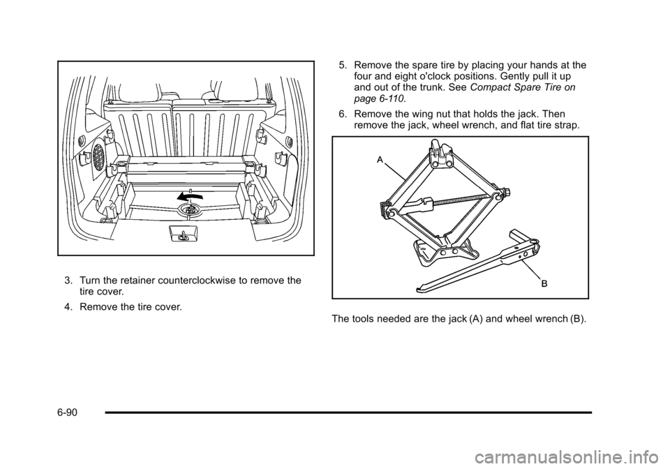
3. Turn the retainer counterclockwise to remove thetire cover.
4. Remove the tire cover. 5. Remove the spare tire by placing your hands at the
four and eight o'clock positions. Gently pull it up
and out of the trunk. See Compact Spare Tire
on
page 6‑110.
6. Remove the wing nut that holds the jack. Then remove the jack, wheel wrench, and flat tire strap.
The tools needed are the jack (A) and wheel wrench (B).
6-90
Page 469 of 480

Headlamps (cont.)High/Low Beam Changer . . . . . . . . . . . . . . . . . . . . . . . . . . 4-5
On Reminder . . . . . . . . . . . . . . . . . . . . . . . . . . . . . . . . . . . . . 4-12
Wiper Activated . . . . . . . . . . . . . . . . . . . . . . . . . . . . . . . . . . . 4-11
Heated Seats . . . . . . . . . . . . . . . . . . . . . . . . . . . . . . . . . . . . . . . .2-6
Heater . . . . . . . . . . . . . . . . . . . . . . . . . . . . . . . . . . . . . . . . . . . . . 4-18 Engine Coolant . . . . . . . . . . . . . . . . . . . . . . . . . . . . . . . . . . . 3-27
Height Adjuster, Driver Seat . . . . . . . . . . . . . . . . . . . . . . . . .2-5
Hideaway Rear Storage Bins . . . . . . . . . . . . . . . . . . . . . . 3-51
Highbeam On Light . . . . . . . . . . . . . . . . . . . . . . . . . . . . . . . . 4-39
Highway Hypnosis . . . . . . . . . . . . . . . . . . . . . . . . . . . . . . . . . 5-19
Hill and Mountain Roads . . . . . . . . . . . . . . . . . . . . . . . . . . . 5-20
Hood Checking Things Under . . . . . . . . . . . . . . . . . . . . . . . . . . . 6-14
Release . . . . . . . . . . . . . . . . . . . . . . . . . . . . . . . . . . . . . . . . . . 6-15
Horn . . . . . . . . . . . . . . . . . . . . . . . . . . . . . . . . . . . . . . . . . . . . . . . . .4-3
How to Wear Safety Belts Properly . . . . . . . . . . . . . . . . 2-19
Hydraulic Clutch . . . . . . . . . . . . . . . . . . . . . . . . . . . . . . . . . . . 6-28
I
Ignition Positions . . . . . . . . . . . . . . . . . . . . . . . . . . . . . . . . . . 3-23
Indicator/Warning LIghts Enhanced Traction System (ETS) . . . . . . . . . . . . . . . . 4-32
Infants and Young Children, Restraints . . . . . . . . . . . . 2-38
Inflation - Tire Pressure . . . . . . . . . . . . . . . . . . . . . . . . . . . . 6-63 Instrument Panel
Brightness . . . . . . . . . . . . . . . . . . . . . . . . . . . . . . . . . . . . . . . . 4-14
Storage Area . . . . . . . . . . . . . . . . . . . . . . . . . . . . . . . . . . . . . 3-47
Instrument Panel Cluster . . . . . . . . . . . . . . . . . . . . . . . . . . 4-24
Integrated Trailer Brake Control System (ITBC) . . . . . . . . . . . . . . . . . . . . . . . . . . . . . 5-32, 5-40
Introduction . . . . . . . . . . . . . . . . . . . . . . . . . . . . . . . . . . . . . . . . . .7-2
J
Jump Starting . . . . . . . . . . . . . . . . . . . . . . . . . . . . . . . . . . . . . . 6-41
K
Keyless Entry
Remote (RKE) System . . . . . . . . . . . . . . . . . . . . . . . . . . . . 3-4
Keyless Entry System . . . . . . . . . . . . . . . . . . . . . . . . . . . . . . .3-4
Keys . . . . . . . . . . . . . . . . . . . . . . . . . . . . . . . . . . . . . . . . . . . . . . . . .3-3
L
Labeling, Tire Sidewall . . . . . . . . . . . . . . . . . . . . . . . . . . . . . 6-56
Lamps Daytime Running (DRL) . . . . . . . . . . . . . . . . . . . . . . . . . . 4-12
Dome . . . . . . . . . . . . . . . . . . . . . . . . . . . . . . . . . . . . . . . . . . . . . 4-14
License Plate . . . . . . . . . . . . . . . . . . . . . . . . . . . . . . . . . . . . . 6-52
Malfunction Indicator . . . . . . . . . . . . . . . . . . . . . . . . . . . . . 4-35
Reading . . . . . . . . . . . . . . . . . . . . . . . . . . . . . . . . . . . . . . . . . . 4-14
i - 7