Page 365 of 472

6. Connect the red positive (+) cable to the positive (+) terminal of the dead battery. Use a
remote positive (+) terminal if the vehicle has one.
7. Do not let the other end touch metal. Connect it to the positive (+) terminal of the good battery. Use a
remote positive (+) terminal if the vehicle has one.
8. Now connect the black negative (−) cable to the negative (−) terminal of the good battery. Use a
remote negative (−) terminal if the vehicle has one.
Do not let the other end touch anything until the
next step. The other end of the negative (−) cable
does not go to the dead battery. It goes to a heavy,
unpainted metal engine part or to a remote
negative (−) terminal on the vehicle with the dead
battery. 9. Connect the other end of the negative (−) cable
at least 18 inches (45 cm) away from the dead
battery, but not near engine parts that move.
The electrical connection is just as good there,
and the chance of sparks getting back to the
battery is much less.
Your vehicle has a remote negative (−) terminal for
this purpose.
10. Now start the vehicle with the good battery and run the engine for a while.
11. Try to start the vehicle that had the dead battery. If it will not start after a few tries, it probably needs
service.
6-53
Page 366 of 472
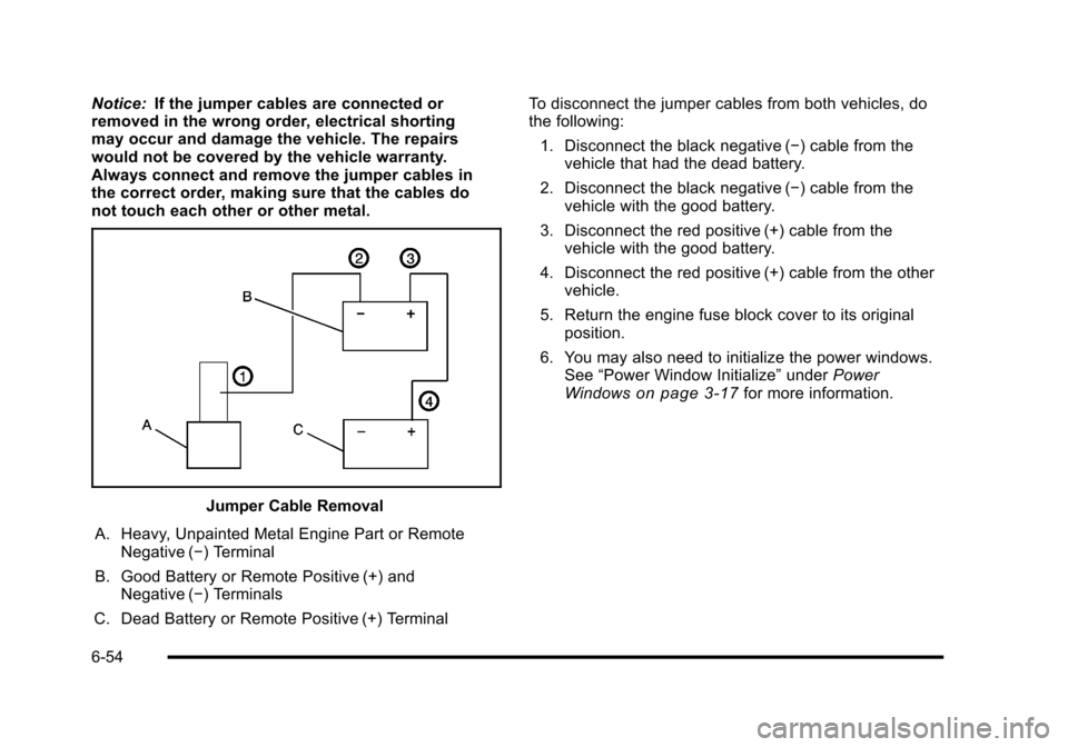
Notice:If the jumper cables are connected or
removed in the wrong order, electrical shorting
may occur and damage the vehicle. The repairs
would not be covered by the vehicle warranty.
Always connect and remove the jumper cables in
the correct order, making sure that the cables do
not touch each other or other metal.
Jumper Cable Removal
A. Heavy, Unpainted Metal Engine Part or Remote Negative (−) Terminal
B. Good Battery or Remote Positive (+) and Negative (−) Terminals
C. Dead Battery or Remote Positive (+) Terminal To disconnect the jumper cables from both vehicles, do
the following:
1. Disconnect the black negative (−) cable from the vehicle that had the dead battery.
2. Disconnect the black negative (−) cable from the vehicle with the good battery.
3. Disconnect the red positive (+) cable from the vehicle with the good battery.
4. Disconnect the red positive (+) cable from the other vehicle.
5. Return the engine fuse block cover to its original position.
6. You may also need to initialize the power windows. See “Power Window Initialize” underPower
Windows
on page 3‑17for more information.
6-54
Page 377 of 472
(F) Uniform Tire Quality Grading (UTQG):Tire
manufacturers are required to grade tires based
on three performance factors: treadwear, traction
and temperature resistance. For more information
see Uniform Tire Quality Grading
on page 6‑79.
(G) Maximum Cold Inflation Load Limit
:
Maximum load that can be carried and the
maximum pressure needed to support that load.
Tire Size
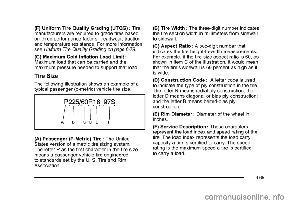
The following illustration shows an example of a
typical passenger (p‐metric) vehicle tire size.
(A) Passenger (P‐Metric) Tire:The United
States version of a metric tire sizing system.
The letter P as the first character in the tire size
means a passenger vehicle tire engineered
to standards set by the U. S. Tire and Rim
Association. (B) Tire Width
:The three‐digit number indicates
the tire section width in millimeters from sidewall
to sidewall.
(C) Aspect Ratio
:A two‐digit number that
indicates the tire height‐to‐width measurements.
For example, if the tire size aspect ratio is 60, as
shown in item C of the illustration, it would mean
that the tire's sidewall is 60 percent as high as it
is wide.
(D) Construction Code
:A letter code is used
to indicate the type of ply construction in the tire.
The letter R means radial ply construction; the
letter D means diagonal or bias ply construction;
and the letter B means belted‐bias ply
construction.
(E) Rim Diameter
:Diameter of the wheel in
inches.
(F) Service Description
:These characters
represent the load index and speed rating of the
tire. The load index represents the load carry
capacity a tire is certified to carry. The speed
rating is the maximum speed a tire is certified
to carry a load.
6-65
Page 396 of 472
Tire Chains
{WARNING:
Do not use tire chains. There is not enough
clearance. Tire chains used on a vehicle without
the proper amount of clearance can cause
damage to the brakes, suspension, or other
vehicle parts. The area damaged by the tire
chains could cause you to lose control of the
vehicle and you or others may be injured in a
crash. Use another type of traction device only
if its manufacturer recommends it for use on
the vehicle and tire size combination and
road conditions. Follow that manufacturer's
instructions. To help avoid damage to the vehicle,
drive slowly, re‐adjust or remove the device if
it is contacting the vehicle, and do not spin the
wheels. If you do find traction devices that will fit,
install them on the rear tires.
Lifting the Vehicle
{WARNING:
Lifting a vehicle can cause an injury. The vehicle
can slip off the jack and roll over you or other
people. You and they could be badly injured.
Find a level place to lift your vehicle. To help
prevent the vehicle from moving: 1. Set the parking brake firmly.
2. Put an automatic transmission shift lever in P (Park), or shift a manual transmission to
1 (First) or R (Reverse).
3. Turn off the engine.
To be even more certain the vehicle won't move,
you can put blocks in front of and behind the
wheels.
6-84
Page 411 of 472
Fiberglass Springs
(Composite Springs)
Notice:
If you use acidic or corrosive cleaning products,
engine degreasers or aluminum cleaning agents on
fiberglass springs, you may damage the springs.
The repairs would not be covered by your warranty.
Use only approved cleaners when cleaning your
vehicle's fiberglass springs.
Chemical Paint Spotting
Some weather and atmospheric conditions can create a
chemical fallout. Airborne pollutants can fall upon and
attack painted surfaces on the vehicle. This damage
can take two forms: blotchy, ring-shaped discolorations,
and small, irregular dark spots etched into the paint
surface.
Although no defect in the paint job causes this, we will
repair, at no charge to the owner, the surfaces of new
vehicles damaged by this fallout condition within
12 months or 12,000 miles (20 000 km) of purchase,
whichever occurs first.
Vehicle Identification
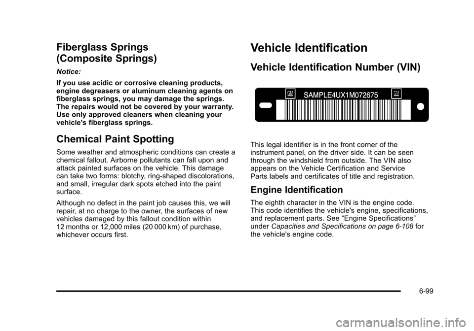
Vehicle Identification Number (VIN)
This legal identifier is in the front corner of the
instrument panel, on the driver side. It can be seen
through the windshield from outside. The VIN also
appears on the Vehicle Certification and Service
Parts labels and certificates of title and registration.
Engine Identification
The eighth character in the VIN is the engine code.
This code identifies the vehicle's engine, specifications,
and replacement parts. See “Engine Specifications”
under Capacities and Specifications
on page 6‑108for
the vehicle's engine code.
6-99
Page 415 of 472
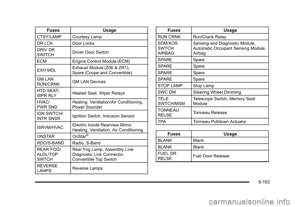
FusesUsage
CTSY/LAMP Courtesy Lamp
DR LCKDoor Locks
DRIV DR
SWITCH Driver Door Switch
ECM Engine Control Module (ECM)
EXH MDL Exhaust Module (Z06 & ZR1),
Spare (Coupe and Convertible)
GM LAN
RUN/CRNK GM LAN Devices
HTD SEAT/
WPR RLY Heated Seat, Wiper Relays
HVAC/
PWR SND Heating. Ventilation/Air Conditioning,
Power Sounder
IGN SWTCH/
INTR SNSR Ignition Switch, Intrusion Sensor
ISRVM/HVAC Electric Inside Rearview Mirror,
Heating, Ventilation, Air Conditioning
ONSTAR OnStar
®
RDO/S‐BAND Radio, S‐Band
REAR FOG/
ALDL/TOP
SWTCH Rear Fog Lamp, Assembly Line
Diagnostic Link Connector,
Convertible Top Switch
REVERSE
LAMPS Reverse Lamps
Fuses
Usage
RUN CRNK Run/Crank Relay
SDM/AOS
SWTCH
AIRBAG Sensing and Diagnostic Module,
Automatic Occupant Sensing Module,
Airbag
SPARE Spare
SPARE Spare
SPARE Spare
SPARE Spare
STOP LAMP Stop Lamp
SWC DM Steering Wheel Dimming
TELE
SWTCH/MSM Telescope Switch, Memory Seat
Module
TONNEAU
RELSE Tonneau Release
TPA Tonneau Pulldown Actuator
Fuses Usage
BLANKBlank
BLANK Blank
FUEL DR
RELSE Fuel Door Release
6-103
Page 416 of 472
FusesUsage
REAR/FOG Rear Fog Lamps
TONNEAU
RELSE Tonneau Release
TRUNK RELSE Trunk Release
Fuses Usage
AUX PWRAuxiliary Power
BLANK Not Used
BLANK Not Used
BLANK Not Used
BLANK Not Used
BLANK Not Used
BLANK Not Used
BLANK Not Used
DRVR
HTD SEAT Driver Heated Seat
LTR Cigarette Lighter
Fuses Usage
PASS
HTD SEAT Passenger Heated Seat
PWR
SEATS MSM Power Seats, Memory Seat Module
PWR/ WNDWS/
TRUNK/FUEL
RELSE Power Windows, Trunk, Fuel Door
Release
TRUNK RELSE Trunk Release
WPR DWELL Wiper Dwell
WPR/WSW Windshield Wiper/Washer
Engine Compartment Fuse Block
There is one fuse block in the engine compartment
located on the passenger side of the vehicle.
See Engine Compartment Overview
on page 6‑14for more information on location.
Notice: Spilling liquid on any electrical components
on the vehicle may damage it. Always keep the
covers on any electrical component.
6-104
Page 418 of 472
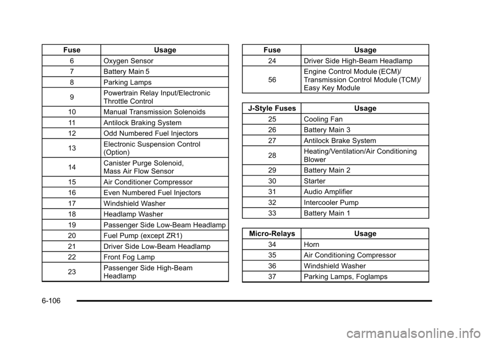
FuseUsage
6Oxygen Sensor
7 Battery Main 5
8 Parking Lamps
9 Powertrain Relay Input/Electronic
Throttle Control
10 Manual Transmission Solenoids
11 Antilock Braking System
12 Odd Numbered Fuel Injectors
13 Electronic Suspension Control
(Option)
14 Canister Purge Solenoid,
Mass Air Flow Sensor
15 Air Conditioner Compressor
16 Even Numbered Fuel Injectors
17 Windshield Washer
18 Headlamp Washer
19 Passenger Side Low-Beam Headlamp
20 Fuel Pump (except ZR1)
21 Driver Side Low-Beam Headlamp
22 Front Fog Lamp
23 Passenger Side High-Beam
Headlamp
Fuse
Usage
24Driver Side High-Beam Headlamp
56 Engine Control Module (ECM)/
Transmission Control Module (TCM)/
Easy Key Module
J-Style Fuses
Usage
25Cooling Fan
26 Battery Main 3
27 Antilock Brake System
28 Heating/Ventilation/Air Conditioning
Blower
29 Battery Main 2
30 Starter
31 Audio Amplifier
32 Intercooler Pump
33 Battery Main 1
Micro-Relays Usage
34Horn
35 Air Conditioning Compressor
36 Windshield Washer
37 Parking Lamps, Foglamps
6-106