2010 CHEVROLET CORVETTE height
[x] Cancel search: heightPage 13 of 472
Seat Adjustment
Manual Seats
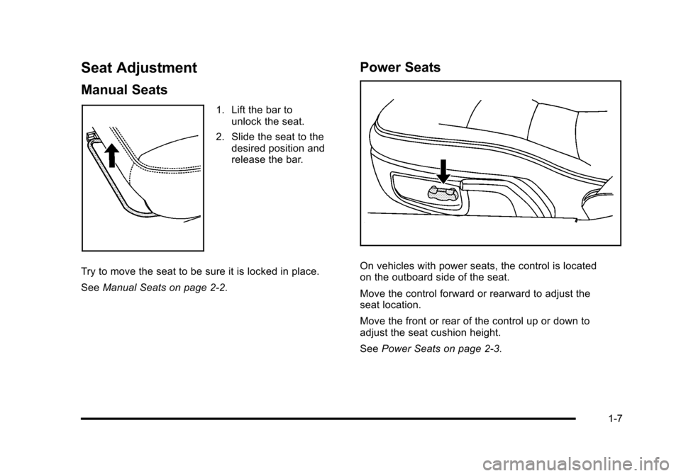
1. Lift the bar to unlock the seat.
2. Slide the seat to the desired position and
release the bar.
Try to move the seat to be sure it is locked in place.
See Manual Seats on page 2‑2.
Power Seats
On vehicles with power seats, the control is located
on the outboard side of the seat.
Move the control forward or rearward to adjust the
seat location.
Move the front or rear of the control up or down to
adjust the seat cushion height.
See Power Seats on page 2‑3.
1-7
Page 37 of 472
Power Seats
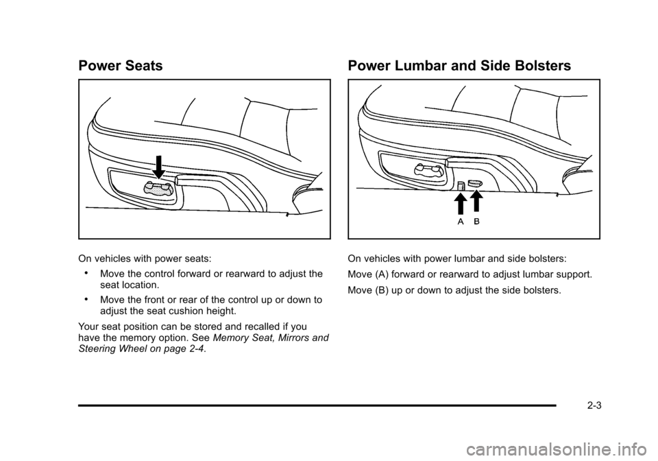
On vehicles with power seats:
.Move the control forward or rearward to adjust the
seat location.
.Move the front or rear of the control up or down to
adjust the seat cushion height.
Your seat position can be stored and recalled if you
have the memory option. See Memory Seat, Mirrors and
Steering Wheel on page 2‑4.
Power Lumbar and Side Bolsters
On vehicles with power lumbar and side bolsters:
Move (A) forward or rearward to adjust lumbar support.
Move (B) up or down to adjust the side bolsters.
2-3
Page 61 of 472
The manufacturer's instructions that come with the
booster seat, state the weight and height limitations for
that booster. Use a booster seat with a lap-shoulder belt
until the child passes the below fit test:
.Sit all the way back on the seat. Do the knees
bend at the seat edge? If yes, continue. If no,
return to the booster seat.
.Buckle the lap-shoulder belt. Does the shoulder
belt rest on the shoulder? If yes, continue. If no,
then return to the booster seat.
.Does the lap belt fit low and snug on the hips,
touching the thighs? If yes, continue. If no, return
to the booster seat.
.Can proper safety belt fit be maintained for the
length of the trip? If yes, continue. If no, return to
the booster seat. Q: What is the proper way to wear safety belts?
A:
An older child should wear a lap-shoulder belt and
get the additional restraint a shoulder belt can
provide. The shoulder belt should not cross the face
or neck. The lap belt should fit snugly below the
hips, just touching the top of the thighs. This applies
belt force to the child's pelvic bones in a crash.
It should never be worn over the abdomen, which
could cause severe or even fatal internal injuries
in a crash.
According to accident statistics, children and infants are
safer when properly restrained in rear seating positions
than in the front seating positions.
In a crash, children who are not buckled up can strike
other people who are buckled up, or can be thrown out
of the vehicle. Older children need to use safety belts
properly.
2-27
Page 66 of 472
Q: What are the different types of add-on child restraints?
A: Add-on child restraints, which are purchased by the
vehicle's owner, are available in four basic types.
Selection of a particular restraint should take into
consideration not only the child's weight, height,
and age but also whether or not the restraint will be
compatible with the motor vehicle in which it will
be used.
For most basic types of child restraints, there are
many different models available. When purchasing a
child restraint, be sure it is designed to be used in a
motor vehicle. If it is, the restraint will have a label
saying that it meets federal motor vehicle safety
standards.
The restraint manufacturer's instructions that come
with the restraint state the weight and height
limitations for a particular child restraint. In addition,
there are many kinds of restraints available for
children with special needs.
{WARNING:
To reduce the risk of neck and head injury during
a crash, infants need complete support. This is
because an infant's neck is not fully developed
and its head weighs so much compared with
the rest of its body. In a crash, an infant in a
rear-facing child restraint settles into the restraint,
so the crash forces can be distributed across the
strongest part of an infant's body, the back and
shoulders. Infants should always be secured in
rear-facing child restraints.
2-32
Page 93 of 472
Adding Equipment to Your
Airbag-Equipped Vehicle
Q: Is there anything I might add to or change about the vehicle that could keep the airbags from
working properly?
A: Yes. If you add things that change your vehicle's
frame, bumper system, height, front end or side
sheet metal, they may keep the airbag system from
working properly. Changing or moving any parts of
the front seats, safety belts, the airbag sensing and
diagnostic module, steering wheel, instrument panel,
the inside review mirror, front sensors, or airbag
wiring can affect the operation of the airbag system.
In addition, the vehicle has a passenger sensing
system for the right front passenger position, which
includes sensors that are part of the passenger seat.
The passenger sensing system may not operate
properly if the original seat trim is replaced with
non-GM covers, upholstery or trim, or with
GM covers, upholstery or trim designed for a
different vehicle. Any object, such as an aftermarket
seat heater or a comfort enhancing pad or device,
installed under or on top of the seat fabric, could also interfere with the operation of the passenger
sensing system. This could either prevent proper
deployment of the passenger airbag(s) or prevent
the passenger sensing system from properly turning
off the passenger airbag(s). See
Passenger Sensing
System
on page 2‑53.
If you have any questions about this, you should
contact Customer Assistance before you modify
your vehicle. The phone numbers and addresses
for Customer Assistance are in Step Two of the
Customer Satisfaction Procedure in this manual.
See Customer Satisfaction Procedure on page 8‑2.
Q: Because I have a disability, I have to get my vehicle modified. How can I find out whether this
will affect my airbag system?
A: If you have questions, call Customer Assistance.
The phone numbers and addresses for Customer
Assistance are in Step Two of the Customer
Satisfaction Procedure in this manual. See
Customer Satisfaction Procedure on page 8‑2.
Your dealer/retailer and the service manual have
information about the location of the airbag sensors,
sensing and diagnostic module and airbag wiring.
2-59
Page 188 of 472
To change the language and unit selections, see
“OPTION” underDIC Operation and Displayson
page 4‑47.
Clean the inside of the windshield as needed to remove
any dirt or film that reduces the sharpness or clarity of
the HUD image.
To clean the HUD, spray household glass cleaner on a
soft, clean cloth. Wipe the HUD lens gently, then dry it.
Do not spray cleaner directly on the lens because the
cleaner could leak into the unit.
If the ignition is on and the HUD image cannot be seen,
check to see if:
.Something is covering the HUD unit.
.The HUD dimmer control is adjusted properly.
.The HUD image is adjusted to the proper height.
.Ambient light is low, in the direction the vehicle is
facing.
.A fuse is blown. See Fuses and Circuit Breakerson page 6‑101.
Keep in mind that the windshield is part of the HUD
system. See Windshield Replacement on page 6‑59.
Accessory Power Outlet(s)
The accessory power outlet can be used to connect
electrical equipment, such as a cellular phone.
The accessory power outlet is located inside the center
console storage compartment, on the forward left side.
To use the outlet, remove the tethered cap. When not
using it, always cover the outlet with the protective cap.
Notice: Leaving electrical equipment plugged in for
an extended period of time while the vehicle is off
will drain the battery. Power is always supplied to
the outlets. Always unplug electrical equipment
when not in use and do not plug in equipment that
exceeds the maximum 20 ampere rating.
Certain electrical accessories may not be compatible
with the accessory power outlet and could result in
blown vehicle or adapter fuses. If you experience
a problem, see your dealer/retailer for additional
information on accessory power outlets.
4-20
Page 360 of 472
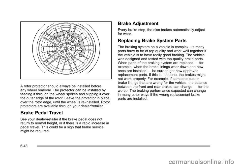
A rotor protector should always be installed before
any wheel removal. The protector can be installed by
feeding it through the wheel spokes and slipping it over
the outer edge of the rotor. Leave the protector in place,
over the rotor edge, until the wheel is re‐installed. Rotor
protectors are available through your dealer/retailer.
Brake Pedal Travel
See your dealer/retailer if the brake pedal does not
return to normal height, or if there is a rapid increase in
pedal travel. This could be a sign that brake service
might be required.
Brake Adjustment
Every brake stop, the disc brakes automatically adjust
for wear.
Replacing Brake System Parts
The braking system on a vehicle is complex. Its many
parts have to be of top quality and work well together if
the vehicle is to have really good braking. The vehicle
was designed and tested with top-quality brake parts.
When parts of the braking system are replaced —for
example, when the brake linings wear down and new
ones are installed —be sure to get new approved
replacement parts. If this is not done, the brakes might
not work properly. For example, if someone puts in
brake linings that are wrong for the vehicle, the balance
between the front and rear brakes can change —for the
worse. The braking performance expected can change
in many other ways if the wrong replacement brake
parts are installed.
6-48
Page 376 of 472
Tire Sidewall Labeling
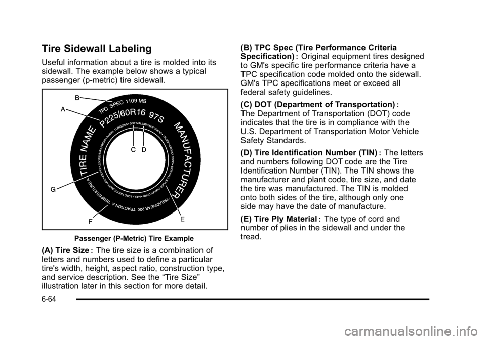
Useful information about a tire is molded into its
sidewall. The example below shows a typical
passenger (p‐metric) tire sidewall.
Passenger (P‐Metric) Tire Example
(A) Tire Size:The tire size is a combination of
letters and numbers used to define a particular
tire's width, height, aspect ratio, construction type,
and service description. See the “Tire Size”
illustration later in this section for more detail. (B) TPC Spec (Tire Performance Criteria
Specification)
:Original equipment tires designed
to GM's specific tire performance criteria have a
TPC specification code molded onto the sidewall.
GM's TPC specifications meet or exceed all
federal safety guidelines.
(C) DOT (Department of Transportation)
:
The Department of Transportation (DOT) code
indicates that the tire is in compliance with the
U.S. Department of Transportation Motor Vehicle
Safety Standards.
(D) Tire Identification Number (TIN)
:The letters
and numbers following DOT code are the Tire
Identification Number (TIN). The TIN shows the
manufacturer and plant code, tire size, and date
the tire was manufactured. The TIN is molded
onto both sides of the tire, although only one
side may have the date of manufacture.
(E) Tire Ply Material
:The type of cord and
number of plies in the sidewall and under the
tread.
6-64