2010 BMW 335I CONVERTIBLE lights
[x] Cancel search: lightsPage 68 of 266

Driving
66
Resuming stored desired speed and
distance
Briefly press the button, arrow 4.
The stored speed and distance are regained
and maintained.
In the following instances, the stored speed is
deleted and can no longer be resumed:
>When driving stability control systems are
intervening
>In cars with ma nual trans mis sio n: when you
shift gears very slowly or shift to neutral
>In cars with automatic transmission: when
you engage selector lever position N
>When the ignition is switched off
Displays in the instrument cluster
1Stored desired speed
2Shows yellow: vehicle detected ahead
Flashes in red: system cannot maintain dis-
tance; driver must brake the vehicle
Flashes in yellow: driving stability control
systems are intervening; cruise control is
deactivated
3Selected distance to vehicle ahead
The indicator lights up as soon as the sys-
tem is activated.
4Selected desired speed is temporarily dis-
played
If --- mph or --- km/h temporarily appears
in the instrument cluster display, it is pos-
sible that the system prerequisites for operation are currently not met. Calling up Check Control
messages, refer to page78.<
Warning lamps
The indicator2 flashes in red; a
signal sounds.
The system indicates that you
must brake and/or maneuver the
vehicle yourself. Active cruise con-
trol cannot automatically restore the distance to
the vehicle ahead.
This indicator does not release you from your
responsibility to adapt your desired speed and
driving style to prevailing driving conditions.
The indicator 2 flashes in yellow.
The prerequisites for operating
active cruise control are not met,
e.g. as a result of ABS or DSC
interventions. Active cruise control
is deactivated. You can reactivate the system, if
desired, by tapping or pulling the lever when
road and traffic conditions permit. It is not pos-
sible to resume a stored speed.
Radar sensor
The sensor's ability to detect vehicles ahead
may be restricted as a result of heavy rain, dirt,
snow or ice. If necessary, clean the radar sensor
located in the front bumper, see arrow. Be sure
to use particular care when removing any layers
of snow or ice from the sensor.
The system cannot be activated if the sensor is
incorrectly aligned.
For US owners only
The transmitter and receiver units comply with
part 15 of the FCC/Federal Communications
Page 71 of 266

Controls
69Reference
At a glance
Driving tips
Communications
Navigation
Entertainment
Mobility
Controls overview
Odometer, outside
temperature display, clock
1Knob in the instrument cluster
2Outside temperature display and clock
3Odometer and trip odometer
Knob in the instrument cluster
>To reset the trip odometer while the ignition
is switched on
>To display the time, outside temperature
and odometer briefly while the ignition is
switched off
Units of measure
T o s e l e c t t h e r e s p e c t i v e u n i t s o f m e a s u r e , m i l e s
or km for the odometer as well as 7 or 6 for
the outside temperature, refer to page72.
The setting is stored for the remote control cur-
rently in use.
Time, outside temperature display
Setting the time, refer to page75.
Outside temperature warning
When the displayed temperature sinks to
approx. +377/+36, a signal sounds and a
warning lamp lights up. There is an increased
risk of black ice.
Black ice can also form at temperatures
above +377/+36. You should there-
fore drive carefully on bridges and shaded roads, for example; otherwise, there is an
increased risk of an accident.<
Odometer and trip odometer
Resetting the trip odometer:
With the ignition switched on, press button1 in
the instrument cluster.
When the vehicle is parked
If you still want to view the time, outside tem-
perature and odometer reading briefly after the
remote control has been taken out of the igni-
tion lock:
Press button 1 in the instrument cluster.
Tachometer
Never force the engine speed up into the red
warning field, see arrow. In this range, the fuel
supply is interrupted to protect the engine.
Page 74 of 266

Controls overview
72
Resetting the Trip computer
You can reset all values:1."Vehicle Info"
2."Trip computer"
3."Reset"
Settings and information
Operating principle
1Button for:
>Selecting display
>Setting values
2Button for:
>Confirming selected display or set val-
ues
>Calling up computer information703When the lights are on: instrument lighting
brightness96
4Calling up Check Control77
5Checking engine oil level213
6Setting the time75
7Setting the date76
8Viewing service requirement display73
Exiting displays
The outside temperature reading and the time
reappear when you press button2 or if you
make no entries within approx. 15 seconds. If
required, complete the current setting first.
Units of measure
Setting the units of measure
You can change the units for fuel consumption,
route/distance, temperature and pressure.
Page 86 of 266
Technology for driving comfort and safety
84
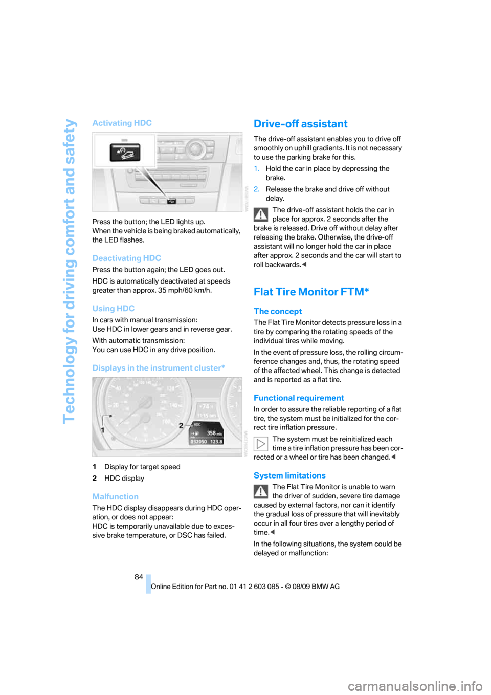
Activating HDC
Press the button; the LED lights up.
When the vehicle is being braked automatically,
the LED flashes.
Deactivating HDC
Press the button again; the LED goes out.
HDC is automatically deactivated at speeds
greater than approx. 35 mph/60 km/h.
Using HDC
In cars with manual transmission:
Use HDC in lower gears and in reverse gear.
With automatic transmission:
You can use HDC in any drive position.
Displays in the instrument cluster*
1Display for target speed
2HDC display
Malfunction
The HDC display disappears during HDC oper-
ation, or does not appear:
HDC is temporarily unavailable due to exces-
sive brake temperature, or DSC has failed.
Drive-off assistant
The drive-off assistant enables you to drive off
smoothly on uphill gradients. It is not necessary
to use the parking brake for this.
1.Hold the car in place by depressing the
brake.
2.Release the brake and drive off without
delay.
The drive-off assistant holds the car in
place for approx. 2 seconds after the
brake is released. Drive off without delay after
releasing the brake. Otherwise, the drive-off
assistant will no longer hold the car in place
after approx. 2 seconds and the car will start to
roll backwards.<
Flat Tire Monitor FTM*
The concept
The Flat Tire Monitor detects pressure loss in a
tire by comparing the rotating speeds of the
individual tires while moving.
In the event of pressure loss, the rolling circum-
ference changes and, thus, the rotating speed
of the affected wheel. This change is detected
and is reported as a flat tire.
Functional requirement
In order to assure the reliable reporting of a flat
tire, the system must be initialized for the cor-
rect tire inflation pressure.
The system must be reinitialized each
time a tire inflation pressure has been cor-
rected or a wheel or tire has been changed.<
System limitations
The Flat Tire Monitor is unable to warn
the driver of sudden, severe tire damage
caused by external factors, nor can it identify
the gradual loss of pressure that will inevitably
occur in all four tires over a lengthy period of
time.<
In the following situations, the system could be
delayed or malfunction:
Page 90 of 266
Technology for driving comfort and safety
88 The status is displayed.
Malfunction
The small warning lamp flashes in
yellow and then lights up continu-
ously; the large warning lamp comes
on in yellow. On the Control Display,
the tires are shown in gray and a message
appears. No punctures can be detected.
This type of message is shown in the following
situations:
>If there is a malfunction
Have the system checked.
>If a wheel without TPM electronics has
been mounted
>If TPM is temporarily malfunctioning due to
other systems or devices using the same
radio frequency.
Message for unsuccessful system
reset
The warning lamp lights up yellow. A
message appears on the Control Dis-
play. The system is not reset, e.g.
after a wheel change.
Check the tire inflation pressure and reset the
system, refer to page86.
Declaration according to NHTSA/
FMVSS 138
Tire Pressure Monitoring Systems
Each tire should be checked monthly when cold
and inflated to the inflation pressure recom-
mended by the vehicle manufacturer on the
vehicle placard or tire inflation pressure label. If
your vehicle has tires of a different size than the
size indicated on the vehicle placard or tire infla-
tion pressure label, you should determine the
proper tire inflation pressure for those tires. As
an added safety feature, your vehicle has been
equipped with a tire pressure monitoring sys-
tem, TPMS, that illuminates a low tire pressure
telltale when one or more of your tires are signif-
icantly underinflated. Accordingly, when the
low tire pressure telltale illuminates, you should
stop and check your tires as soon as possible,
and inflate them to the proper pressure. Driving on a significantly underinflated tire causes the
tire to overheat and can lead to tire failure.
Underinflation also reduces fuel efficiency and
tire tread life, and may affect the vehicle’s han-
dling and stopping ability. Please note that the
TPMS is not a substitute for proper tire mainte-
nance, and it is the driver’s responsibility to
maintain correct tire pressure, even if underin-
flation has not reached the level at which the
TPMS low tire pressure telltale illuminates.
The TPMS malfunction indicator is combined
with the low tire pressure telltale. When the sys-
tem detects a malfunction, the telltale will flash
for approximately one minute and then remain
continuously lit. This sequence will continue
upon subsequent vehicle startups as long as
the malfunction exists. When the malfunction
indicator is illuminated, the system may not be
able to detect or signal low tire pressure as
intended. TPMS malfunctions may occur for a
variety of reasons, including the installation of
replacement or alternate tires or wheels on the
vehicle that prevent the TPMS from functioning
properly. Always check the TPMS malfunction
telltale after replacing one or more tires or
wheels on your vehicle to ensure that the
replacement or alternate tires and wheels allow
the TPMS to continue to function properly.
Active steering*
The concept
Active steering varies the turning angle of the
front wheels in relation to steering wheel move-
ments. It also varies the steering force required
to turn the wheels depending on the speed at
which you are driving.
When you are driving in the low road speed
range, e.g. in a town or when parking, the steer-
ing angle is increased, i.e. steering becomes
very direct and less effort is required to turn the
wheels. In the higher speed range, on the other
hand, the steering angle is reduced as the
speed increases. This improves the handling of
your BMW over the entire speed range.
Page 93 of 266
Controls
91Reference
At a glance
Driving tips
Communications
Navigation
Entertainment
Mobility
activated, refer to Status of front passenger air-
bags below.<
Before transporting a child on the front
passenger seat, read the safety precau-
tions and handling instructions under Trans-
porting children safely, refer to page52.
The front and side airbags can also be deacti-
vated by adolescents and adults sitting in cer-
tain positions; the indicator lamp for the front
passenger airbags comes on. In such cases, the
passenger should change his or her sitting
position so that the front passenger airbags are
activated and the indicator lamp goes out. If the
desired airbag status cannot be achieved by
changing the sitting position, transport the rele-
vant passenger on a rear seat. Do not attach
seat covers, seat cushion padding, ball mats or
other items to the front passenger seat unless
they are specifically recommended by BMW.
Do not place any items under the seat which
could press against the seat from below. Other-
wise, a correct analysis of the seat cushion is
not ensured.<
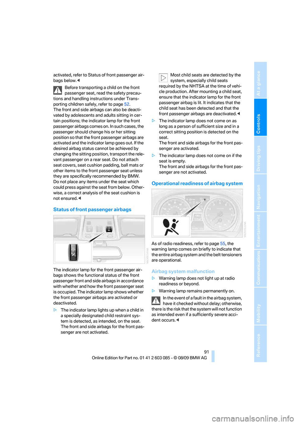
Status of front passenger airbags
The indicator lamp for the front passenger air-
bags shows the functional status of the front
passenger front and side airbags in accordance
with whether and how the front passenger seat
is occupied. The indicator lamp shows whether
the front passenger airbags are activated or
deactivated.
>The indicator lamp lights up when a child in
a specially designated child restraint sys-
tem is detected, as intended, on the seat.
The front and side airbags for the front pas-
senger are not activated.Most child seats are detected by the
system, especially child seats
required by the NHTSA at the time of vehi-
cle production. After mounting a child seat,
ensure that the indicator lamp for the front
passenger airbag is lit. It indicates that the
child seat has been detected and that the
front passenger airbags are deactivated.<
>The indicator lamp does not come on as
long as a person of sufficient size and in a
correct sitting position is detected on the
seat.
The front and side airbags for the front pas-
senger are activated.
>The indicator lamp does not come on if the
seat is empty.
The front and side airbags for the front pas-
senger are not activated.
Operational readiness of airbag system
As of radio readiness, refer to page55, the
warning lamp comes on briefly to indicate that
the entire airbag system and the belt tensioners
are operational.
Airbag system malfunction
>Warning lamp does not light up at radio
readiness or beyond.
>Warning lamp remains permanently on.
In the event of a fault in the airbag system,
have it checked without delay; otherwise,
there is the risk that the system will not function
as intended even if a sufficiently severe acci-
dent occurs.<
Page 95 of 266
Controls
93Reference
At a glance
Driving tips
Communications
Navigation
Entertainment
Mobility
Lamps
Parking lamps/low beams
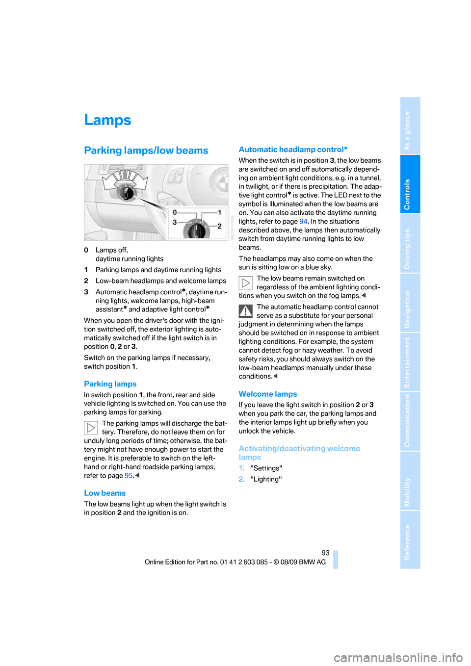
0Lamps off,
daytime running lights
1Parking lamps and daytime running lights
2Low-beam headlamps and welcome lamps
3Automatic headlamp control
*, daytime run-
ning lights, welcome lamps, high-beam
assistant
* and adaptive light control*
When you open the driver's door with the igni-
tion switched off, the exterior lighting is auto-
matically switched off if the light switch is in
position 0, 2 or 3.
Switch on the parking lamps if necessary,
switch position 1.
Parking lamps
In switch position1, the front, rear and side
vehicle lighting is switched on. You can use the
parking lamps for parking.
The parking lamps will discharge the bat-
tery. Therefore, do not leave them on for
unduly long periods of time; otherwise, the bat-
tery might not have enough power to start the
engine. It is preferable to switch on the left-
hand or right-hand roadside parking lamps,
refer to page95.<
Low beams
The low beams light up when the light switch is
in position 2 and the ignition is on.
Automatic headlamp control*
When the switch is in position3, the low beams
are switched on and off automatically depend-
ing on ambient light conditions, e.g. in a tunnel,
in twilight, or if there is precipitation. The adap-
tive light control
* is active. The LED next to the
symbol is illuminated when the low beams are
on. You can also activate the daytime running
lights, refer to page94. In the situations
described above, the lamps then automatically
switch from daytime running lights to low
beams.
The headlamps may also come on when the
sun is sitting low on a blue sky.
The low beams remain switched on
regardless of the ambient lighting condi-
tions when you switch on the fog lamps.<
The automatic headlamp control cannot
serve as a substitute for your personal
judgment in determining when the lamps
should be switched on in response to ambient
lighting conditions. For example, the system
cannot detect fog or hazy weather. To avoid
safety risks, you should always switch on the
low-beam headlamps manually under these
conditions.<
Welcome lamps
If you leave the light switch in position 2 or 3
when you park the car, the parking lamps and
the interior lamps light up briefly when you
unlock the vehicle.
Activating/deactivating welcome
lamps
1."Settings"
2."Lighting"
Page 96 of 266
Lamps
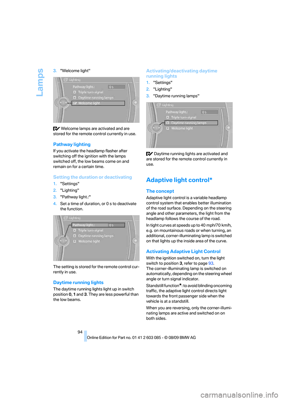
94 3."Welcome light"
Welcome lamps are activated and are
stored for the remote control currently in use.
Pathway lighting
If you activate the headlamp flasher after
switching off the ignition with the lamps
switched off, the low beams come on and
remain on for a certain time.
Setting the duration or deactivating
1."Settings"
2."Lighting"
3."Pathway light.:"
4.Set a time of duration, or 0 s to deactivate
the function.
The setting is stored for the remote control cur-
rently in use.
Daytime running lights
The daytime running lights light up in switch
position 0, 1 and 3. They are less powerful than
the low beams.
Activating/deactivating daytime
running lights
1."Settings"
2."Lighting"
3."Daytime running lamps"
Daytime running lights are activated and
are stored for the remote control currently in
use.
Adaptive light control*
The concept
Adaptive light control is a variable headlamp
control system that enables better illumination
of the road surface. Depending on the steering
angle and other parameters, the light from the
headlamp follows the course of the road.
In tight curves at speeds up to 40 mph/70 km/h,
e.g. on mountainous roads or when turning, an
additional, corner-illuminating lamp is switched
on that lights up the inside area of the curve.
Activating Adaptive Light Control
With the ignition switched on, turn the light
switch to position 3, refer to page93.
The corner-illuminating lamp is switched on
automatically, depending on the steering wheel
angle or turn signal indicator.
Standstill function
*: to avoid blinding oncoming
traffic, the adaptive light control directs light
towards the front passenger side when the
vehicle is at a standstill.
When you are reversing, only the corner-illumi-
nating lamps are active and switched on on
both sides.