2010 ASTON MARTIN V8 VANTAGE check oil
[x] Cancel search: check oilPage 614 of 947

Power Steering (11.02)
Steering (11.00)
Issue 5, January 2010 Workshop Manual 11-2-11
41. Install the clip that attaches the air intake pipe to the throttle body.
Figure 49
42. Remove and discard the sealing plugs from the two breather pipes and the air intake pipe.
43. Connect the two breather pipes to the air intake pipe.
Figure 50
44. Install the radiator closing panel (refer to Workshop Manual procedure 01.02.AA - Radiator Closing Panel).
45. Fill the oil tank with the correct quantity of oil.
46. Fill the PAS fluid reservoir with the correct quantity of
PAS fluid.
47. Connect the battery ground cable.
48. Bleed the PAS system.
49. Do a check of the engine oi l level. Add oil if necessary.
50. Lift the vehicle.
51. Install the front right side wheel-arch liner (refer to Workshop Manual procedure 01.02.GB - Front Right
Side Wheel-Arch Liner).
52. Install the front wheels and tyres (refer to Workshop Manual procedure 04.04.ED - Wheel and Tyre - Pair)
53. Do a check of the four-wheel alignment.
54. Use the applicable equipment to lift the vehicle and make it safe.
55. Install the front undertray (refer to Workshop Manual procedure 01.02.NB - Front Undertray).
RH/LH Track Rod End-Renew
Removal
1. Raise vehicle on ramp.
2. Remove road wheel(s).
3. Loosen tie rod locknut.
4. Install tool (204 - 524) on front hub, install and tighten
wheel nuts.
5. Lower vehicle to raise suspension sufficient to install ball joint removing tool (204 - 523).
6. Remove nut, track rod end to vertical link.
7. Using (204-523 Ball Joint Sp litter), release track rod end
from vertical link.
8. Remove tool (204 - 524) from front hub.
9. Count number of turns and remove track rod end from tie rod.
Installation
1. Clean track rod end taper and mating face on vertical link.
2. Install track rod end on tie rod the same amount of turns.
3. Install track rod end in vertical link.
4. Install road wheel(s).
5. Lower vehicle on ramp.
6. Carry out full vehicle geometry check/adjust.
7. Torque tie rod ball joint locknut(s).
Power Steering Pump to Rack Hose
Assembly-Renew
Repair Operation Time (ROT)
Repair Operation Time (ROT)
Page 643 of 947

Air Conditioning (A/C) System (12.03)
Climate Control (12.00)
12-3-10 Workshop Manual May 2007
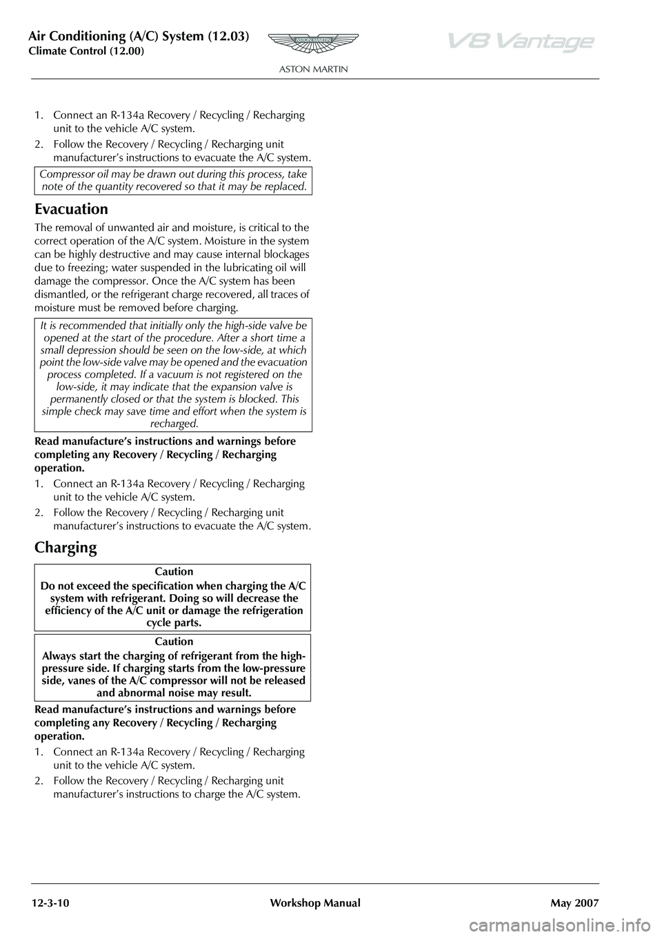
1. Connect an R-134a Recovery / Recycling / Recharging
unit to the vehicle A/C system.
2. Follow the Recovery / Recycling / Recharging unit manufacturer’s instructions to evacuate the A/C system.
Evacuation
The removal of unwanted air and moisture, is critical to the
correct operation of the A/C system. Moisture in the system
can be highly destructive and may cause internal blockages
due to freezing; water suspended in the lubricating oil will
damage the compressor. Once the A/C system has been
dismantled, or the refrigerant charge recovered, all traces of
moisture must be removed before charging.
Read manufacture’s instruct ions and warnings before
completing any Recovery / Recycling / Recharging
operation.
1. Connect an R-134a Recovery / Recycling / Recharging unit to the vehicle A/C system.
2. Follow the Recovery / Recycling / Recharging unit manufacturer’s instructions to evacuate the A/C system.
Charging
Read manufacture’s instruct ions and warnings before
completing any Recovery / Recycling / Recharging
operation.
1. Connect an R-134a Recovery / Recycling / Recharging unit to the vehicle A/C system.
2. Follow the Recovery / Recycling / Recharging unit manufacturer’s instructions to charge the A/C system.
Compressor oil may be drawn ou
t during this process, take
note of the quantity recovered so that it may be replaced.
It is recommended that initiall y only the high-side valve be
opened at the start of the pr ocedure. After a short time a
small depression should be seen on the low-side, at which
point the low-side valve may be opened and the evacuation
process completed. If a vacuum is not registered on the
low-side, it may indicate that the expansion valve is
permanently closed or that th e system is blocked. This
simple check may save time and effort when the system is
recharged.
Caution
Do not exceed the specificat ion when charging the A/C
system with refrigerant. Doing so will decrease the
efficiency of the A/C unit or damage the refrigeration cycle parts.
Caution
Always start the charging of refrigerant from the high-
pressure side. If charging st arts from the low-pressure
side, vanes of the A/C compressor will not be released and abnormal noise may result.
Page 645 of 947

Air Conditioning (A/C) System (12.03)
Climate Control (12.00)
12-3-12 Workshop Manual May 2007
Leaks
Faults associated with low refrigerant charge weight and low pressure may be caused by leakage. Leaks traced to
mechanical connections may be caused by torque relaxation or joint face contamination. Evidence of oil around such
areas is an indicator of leakage.
Leak Detection
Fluorescent Tracer Dye - A fluorescent tracer dye is incorporated into th e refrigeration system and can be checked for
non-apparent leaks by scanning with a high intensity ultraviolet lamp. The location of leaks can be pinpointed by the bright
yellow glow of the tracer dye.
Automatic Refrigerant Leak Detector - (various manufacturers) Hand-held, portable, battery operated leak detector.
Place in and around A/C system to detect refrigerant leaks.
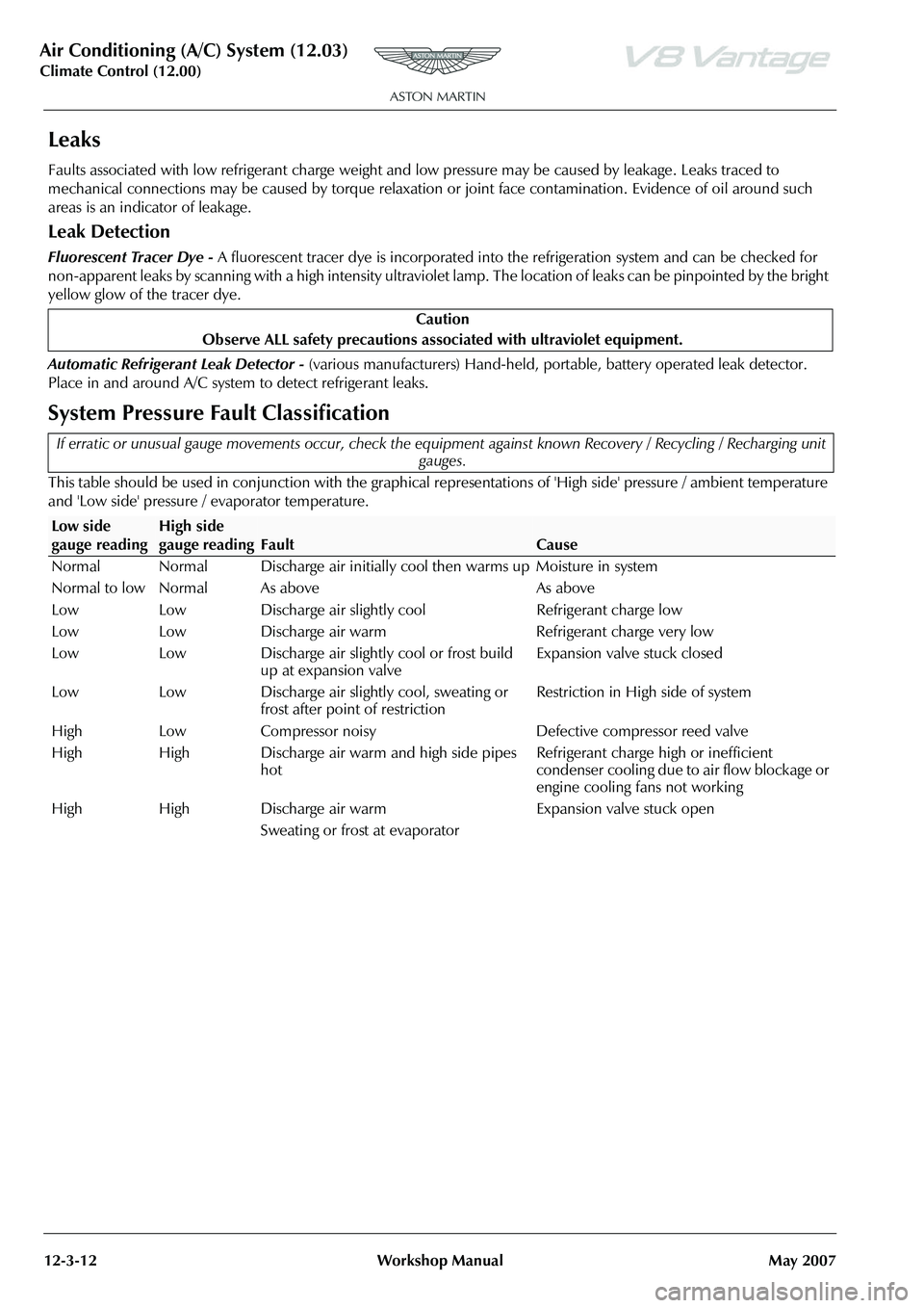
System Pressure Fault Classification
This table should be used in conjunction with the graphical representations of 'High side' pressure / ambient temperature
and 'Low side' pressure / evaporator temperature. Caution
Observe ALL safety precautions associ ated with ultraviolet equipment.
If erratic or unusual gauge movements occur, check the equipment against known Recovery / Recycling / Recharging unit
gauges.
Low side
gauge readingHigh side
gauge reading
Fault
Cause
Normal Normal Discharge air initially c ool then warms up Moisture in system
Normal to low Normal As above As above
Low Low Discharge air slightly cool Refrigerant charge low
Low Low Discharge air warm Refrigerant charge very low
Low Low Discharge air slightly cool or frost build up at expansion valve Expansion valve stuck closed
Low Low Discharge air slightly cool, sweating or frost after point of restriction Restriction in High side of system
High Low Compressor noisy Defective compressor reed valve
High High Discharge air warm and high side pipes hot Refrigerant charge high or inefficient
condenser cooling due to air flow blockage or
engine cooling fans not working
High High Discharge air warm
Sweating or frost at evaporator Expansion valve stuck open
Page 650 of 947

Air Conditioning (A/C) System (12.03)
Climate Control (12.00)
May 2007 Workshop Manual 12-3-17
Symptom (7)DescriptionPossible Cause
Air from vents not cold enough. Magnetic clutch operates but A/
C system malfunctions. • Drive belt fault
• Fault in blower unit or condenser
• Fault in Receiver / Drier or expansion valve
(valve closes too much)
• Fault in refrigerant lines
• A/C compressor system fault, insufficient compressor oil
• Over filling of compressor oil, fault in expansion valve or A/C unit air mix link system
Symptom (8)Possible Cause
No cool air. Magnetic clutch does not
operate. • Fault in PCM A/C cut control system
• Fault in A/C Module
• Fault in refrigerant pressure switch
• Fault in PCM (A/C signal)
• Fault in PCM (IG1 signal)
• Fault in A/C compressor
•Fault in A/C relay
• Fault in Evaporator Temperature Sensor
Shake the wiring harness and connectors wh ile performing the inspection to discover whether poor contact points are the
cause of any intermittent malfunctions. If there is a problem, check to make sure connectors, terminals and wiring harnesses
are connected correctly and undamaged.
Symptom (9)Possible Cause
Noise while operating A/C
system. Noise from magnetic clutch, A/C
compressor, hose or refrigerant
line. • Magnetic clutch operation noise
• A/C compressor slippage noise
• Hose or refrigerant line interference noise
Page 654 of 947

Instrument Cluster (13.01)
Information, Gauge and Warning (13.00)
May 2007 Workshop Manual 13-1-3
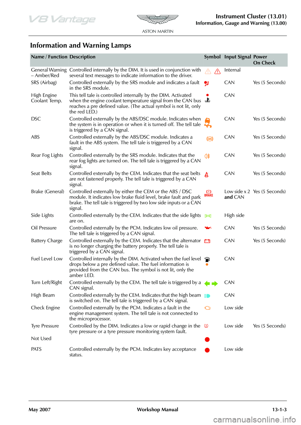
Information and Warning Lamps
Name / FunctionDescriptionSymbolInput SignalPower
On Check
General Warning
– Amber/Red Controlled internally by the DIM. It is used in conjunction with
several text messages to indicate information to the driver. Internal
SRS (Airbag) Controlled externally by the SRS module and indicates a fault in the SRS module. CAN Yes (5 Seconds)
High Engine
Coolant Temp. This tell tale is controlled internally by the DIM. Activated
when the engine coolant temperature signal from the CAN bus
reaches a pre defined value. (The
actual symbol is not lit, only
the red LED.) CAN
DSC Controlled externally by the ABS/DSC module. Indicates when the system is in operation or when it is turned off. The tell tale
is triggered by a CAN signal. CAN Yes (5 Seconds)
ABS Controlled externally by th e ABS/DSC module. Indicates a
fault in the ABS system. The tell tale is triggered by a CAN
signal. CAN Yes (5 Seconds)
Rear Fog Lights Controlled externally by the SRS module. Indicates that the
rear fog lights are turned on. The tell tale is triggered by a CAN
signal. CAN Yes (5 Seconds)
Seat Belts Controlled externally by the CEM. Indicates that the seat belts are not fastened properly. The tell tale is triggered by a CAN
signal. CAN Yes (5 Seconds)
Brake (General) Controlled externally by either the CEM or the ABS / DSC module. It indicates low brake fluid level, brake fault and park
brake. The tell tale is triggered by two low side inputs or a CAN
signal. Low side x 2
and
CAN Ye s ( 5 S e c o n d s )
Side Lights Controlled externally by th e CEM. Indicates that the side lights
are on. High side
Oil Pressure Controlled exte rnally by the PCM. Indicates low oil pressure.
The tell tale is triggered by a CAN signal. CAN Yes (5 Seconds)
Battery Charge Controlled externally by th e CEM. Indicates that the alternator
is no longer charging the battery properly. The tell tale is
triggered by a CAN signal. CAN Yes (5 Seconds)
Fuel Level Low Controlled internally by the DIM. Activated when the fuel level drops below a pre defined value. The fuel information is
provided from the CAN bus. The symbol is not lit, only the
amber LED. CAN
Turn Left/Right Controlled externally by th e CEM. The tell tale is triggered by a
CAN signal. CAN
High Beam Controlled externally by the CEM. Indicates that the high beam is switched on. The tell tale is triggered by a CAN signal. CAN
Check Engine Controlled externally by the PCM. Indicates a fault in the engine management system. The te ll tale is not connected to
the microprocessor. Low side
Tyre Pressure Controlled by the DIM. In dicates a low or rapid change in the
tyre pressure or a tyre pressure monitoring system fault. Low side Yes (5 Seconds)
Not Used
PATS Controlled externally by the PCM. Indicates key acceptance status. Low side
Page 751 of 947

Maintenance Schedules
Appendix & Glossary20-1-12 Workshop Manual May 2007
Maintenance Schedules
1000mls
1500km
3 months10000mls
16000km
12 months20000mls
32000km
24 months
Pre-maintenance
x x x Pre-Maintenance Road Test Evaluation.
x x x Install vehicle protection kit and wing covers.
x x x Check Bulletins/Field Service Actions/Recall Status.
Fluids, Filters and Leaks Checks x - - Check/top-up engine oil level.- x x Renew engine oil and filter. Clean sump filters.
x x x Check for engine oil leaks. Every 48,000km
(30,000 miles)/3 Years Renew air cleaner elements.
Every 32,000km
(20,000 miles)/2 Years Renew air cleaner elements - extreme environments.
x x - Check transaxle for leaks.
Every
32,000km (20,000
miles)/3 Ye a r s Every
96,000km (60,000
miles)/6 Ye a r s Every
160,000km (100,000
miles)/10 years Check/top-up transaxle oil levels.
Every 64,000km
(40,000 miles)/4 Years Renew transaxle oil and clean filter.
Every 160,000km
(100,000 miles)/5 Years Renew engine coolant-ensure 50/50 concentration.
x x x Check/top-up engine coolant.
x x x Check for fuel leaks. Every 2 Years Renew brake/clutch fluid.
- x x Check/top-up brake/clutch fluid reservoir.
x x x Check power steering system for leaks.
x x x Check brake hoses, pipes and unions for leaks.
x x x Check suspension dampers for leaks.
x x x Top-up windscreen/headlamp washer reservoir.
x x x Check exhaust system for leaks.
x x x Check A/C system for leaks. - - x Renew pollen filter.
x x x Check/top-up power steering fluid.
Page 871 of 947

AML EOBD System Operation Summary
Rory O’Curry Aston Martin Lagonda CONFIDENTIAL 1 May 2009
[email protected] AML EOBD Monitors 07 ROC.doc Page 25 of 43
VCT Monitor
Variable Cam Timing System Monitor
VCT Hardware
Variable Cam Timing (VCT) enables rotation of the camshaft(s) relative to the crankshaft (phase-shifting)
as a function of engine operating conditions. Intake Only (phase-shifting only the intake cam) is used in
the AML application.
VCT is used primarily to increase internal residua l dilution at part throttle to reduce NOx, and to
improve fuel economy. With Intake Only VCT, the in take camshaft is advanced at part throttle and WOT
(at low to mid-range engine speeds) to open the in take valve earlier for increased residual dilution and
close the intake valve earlier in the compression stroke for increased power. When the engine is cold,
opening the intake valve earlier warms the charge which improves fuel vaporization for less HC
emissions; when the engine is warm, the residua l burned gasses limit peak combustion temperature to
reduce NOx formation.
The VCT system hardware consists of a contro l solenoid and a pulse ring on the camshaft. The PCM
calculates relative cam position using the CMP input to process variable reluctance sensor pulses coming
from the pulse ring mounted on the camshaft. Each pul se wheel has N + 1 teeth where N = the number of
cylinders per bank. The N equally spaced teeth are used for cam phasing; the remaining tooth is used to
determine cylinder # 1 position. Relative cam position is calculated by measuring the time between the
rising edge of profile ignition pickup (PIP ) and the falling edges of the VCT pulses.
VCT Diagnostic
The PCM continually calculates a cam position error value based on the difference between the desired
and actual position and uses this information to cal culate a commanded duty cycle for the VCT solenoid
valve. When energized, engine oil is allowed to flow to the VCT unit thereby advancing and retarding cam
timing. The VCT logic calculates the instantaneous va riance in actual cam position (the squared difference
between actual cam position and commanded cam position), then calculates the long term variance using a
rolling average filter (Exponentially Weighted Moving Average).
If the VCT system is stuck or operates with an consta nt error relative to the target position, the monitor
will detect a variance which will quickly accumulate. There are three variance indices that monitor cam
variance in the retard direction, the advance directi on, and for V engines, the difference between banks. If
any variance index is greater than the malfunction threshold, a VCT target error malfunction will be
indicated (P0011, P0012 Bank 1, P0021, P0022 Bank 2).
The VCT solenoid output driver in the PCM is check ed electrically for open circuit and shorts (P0010
Bank 1, P0020 Bank 2).
VCT Monitor Operation:
Page 873 of 947

AML EOBD System Operation Summary
Rory O’Curry Aston Martin Lagonda CONFIDENTIAL 1 May 2009
[email protected] AML EOBD Monitors 07 ROC.doc Page 27 of 43
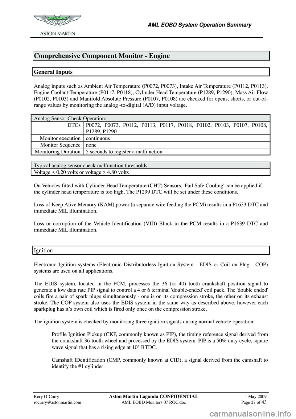
Comprehensive Component Monitor - Engine
General Inputs
Analog inputs such as Ambient Air Temperature (P0072, P0073), Intake Air Temperature (P0112, P0113),
Engine Coolant Temperature (P0117, P0118), Cylinder Head Temperature (P1289, P1290), Mass Air Flow
(P0102, P0103) and Manifold Absolute Pressure (P0107, P0108) are checked for opens, shorts, or out-of-
range values by monitoring the analog -to-digital (A/D) input voltage.
Analog Sensor Check Operation:
DTCs P0072, P0073, P0112, P0113, P0117, P0118, P0102, P0103, P0107, P0108,
P1289, P1290
Monitor execution continuous
Monitor Sequence none
Monitoring Duration 5 seconds to register a malfunction
Typical analog sensor check malfunction thresholds:
Voltage < 0.20 volts or voltage > 4.80 volts
On Vehicles fitted with Cylinder Head Temperature (CHT ) Sensors, 'Fail Safe Cooling' can be applied if
the cylinder head temperature is too high. The P1299 DTC will be set under these conditions.
Loss of Keep Alive Memory (KAM) power (a separate wire feeding the PCM) results in a P1633 DTC and
immediate MIL illumination.
Loss or corruption of the Vehicle Identification (VID) Block in the PCM results in a P1639 DTC and
immediate MIL illumination.
Ignition
Electronic Ignition systems (Electronic Distributorless Ignition System - EDIS or Coil on Plug - COP)
systems are used on all applications.
The EDIS system, located in the PCM, processes the 36 (or 40) tooth crankshaft position signal to
generate a low data rate PIP signal to control a 4 or 6 terminal 'double-ended' coil pack. The 'double ended'
coils fire a pair of spark plugs simultaneously - one is on its compression stroke, the other on its exhaust
stroke. The COP system also uses the EDIS system in the same way as described above, however each
sparkplug has it’s own coil which is fired only once on the compression stroke.
The ignition system is checked by monitoring three ignition signals during normal vehicle operation:
Profile Ignition Pickup (CKP, commonly known as PIP), the timing reference signal derived from the crankshaft 36-tooth wheel and processed by the EDIS system. PIP is a 50% duty cycle, square
wave signal that has a rising edge at 10 ° BTDC.
Camshaft IDentification (CMP, commonly known at CID), a signal derived from the camshaft to identify the #1 cylinder