Page 41 of 271

39
SAFETY
DEVICES
WARNING
LIGHTS AND
MESSAGES
IN AN
EMERGENCY
CAR
MAINTENANCE
TECHNICAL
SPECIFICATIONS
INDEX
DASHBOARD
AND
CONTROLS
CORRECT USE
OF THE CARTRIP BUTTON
ButtonTRIP fig. 24, set on the right
steering column stalk shall be used (with
electronic key into ignition device) to en-
ter the “General Trip” and “Trip B” func-
tion. To scroll the values of each option
use buttons set aside the stalk.ButtonTRIPshall also be used to reset
the “General Trip” and “Trip B” functions
to start a new mission:
❒ short push: to display the differ-
ent values;
❒ long push: to reset and then start
a new mission.
To scroll the Trip Computer options,
briefly press buttons
-and..
New mission (reset)
Reset can be:
❒“manual”, reset is performed by the
driver by pressing button TRIP;
❒“automatic”, reset is performed
when the trip distance reaches
9999.9 km (or mi), when travel
time reaches 99.59 (99 hours and
59 minutes) or after disconnecting
and then reconnecting the battery.
A0F0076mfig. 24
Page 42 of 271

40
SAFETY
DEVICES
WARNING
LIGHTS AND
MESSAGES
IN AN
EMERGENCY
CAR
MAINTENANCE
TECHNICAL
SPECIFICATIONS
INDEX
DASHBOARD
AND
CONTROLS
CORRECT USE
OF THE CARIMPORTANT“General Trip” reset will
also reset the “Trip B” function, where-
as “Trip B” reset will only reset the in-
formation associated with this function.
Every Trip computer screen displays two
options of the active Trip (Trip A or Trip
B); one option is displayed at the top of
the screen, the other one at the bottom
(seefig. 25).In the same screen it is not possible to
have displayed at the same time the
same option at the top and at the bot-
tom of the screen.
Briefly press button TRIPto select the
two Trip computer modes; use button
-to scroll the options at the top of the
display, use button
.to scroll the op-
tions at the bottom of the display.
Press briefly button TRIPto go from
Trip A to Trip B.Start of journey procedure
(reset)
Trip A and Trip B reset are independent.
Reset General Trip
With electronic key into ignition device,
to reset the “General Trip” press and
keep pressed button TRIPfor over 2
seconds.
IMPORTANTReset can be automat-
ic only in the following cases:
❒when the “Travel Distance” reach-
es 9999.9 km or the “Travel Time”
reaches 99.59 (99 hours and 59
minutes);
❒after disconnecting/reconnecting
the battery.
At General Trip reset a warning message
will be displayed.
A0F0052mfig. 25
Page 43 of 271

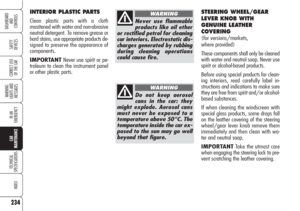
Upholstery of your car
has been designed to
withstand wear deriv-
ing from common use of the car.
You are however recommended
to avoid strong and/or contin-
uous scratching with clothing ac-
cessories such as metallic buck-
les, studs, Velcro fastenings and
the like, since these items cause
circumscribed stress of the cov-
er fabric that could lead to yarn
breaking, and damage the cov-
er as a consequence.
41
SAFETY
DEVICES
WARNING
LIGHTS AND
MESSAGES
IN AN
EMERGENCY
CAR
MAINTENANCE
TECHNICAL
SPECIFICATIONS
INDEX
DASHBOARD
AND
CONTROLS
CORRECT USE
OF THE CAR
Height adjustment
(where provided)
Move repeatedly lever Bupwards or
downwards to achieve the required
height.
IMPORTANTAdjustment must be car-
ried out only seated at the driver’s seat.
Back rest angle adjustment
Operate button Cuntil obtaining the re-
quired position.
SEATS
MANUALLY ADJUSTABLE
FRONT SEATS fig. 26
Only make adjustments
when the car is sta-
tionary.
WARNING
A0F0020mfig. 26
Once you have re-
leased the lever, check
that the seat is firmly locked
in the runners by trying to
move it back and forth. Failure
to lock the seat in place could
result in the seat moving sud-
denly and the driver losing
control of the car.
WARNING
Moving the seat backwards
or forwards
Lift the lever A(on the inner side of the
seat) and push the seat forwards or
backwards: in the driving position the
arms should rest on the rim of the steer-
ing wheel.
Page 44 of 271

Lumbar adjustment
(for versions/markets,
where provided)
Turn the knob Duntil obtaining the re-
quired position.
Back rest angle adjustment
(for versions/markets,
where provided)
Use lever E. Pulling the lever upwards
the seat will bend back by one position.
Pushing the lever downwards the seat
will bend forward.
Tilting the back rest
To get to the rear seats, pull handle F:
the back rest will tilt and the seat can
slide forward.
Bringing back the back rest the seat will
return automatically to its original posi-
tion (mechanical memory).
After bringing the back rest to its origi-
nal position check tat it firmly locked.
Check also that the seat is firmly locked
in the runners by trying to move it back
and forth.
42
SAFETY
DEVICES
WARNING
LIGHTS AND
MESSAGES
IN AN
EMERGENCY
CAR
MAINTENANCE
TECHNICAL
SPECIFICATIONS
INDEX
DASHBOARD
AND
CONTROLS
CORRECT USE
OF THE CAR
ELECTRICALLY ADJUSTABLE
FRONT SEATS fig. 27
(for versions/markets,
where provided)Seat controls are the
following:
Multifunction control A:
❒front seat height adjustment;
❒rear seat height adjustment;
❒vertical seat movement;
❒longitudinal seat movement;
B:Back rest angle adjustment;
C:Driver’s seat positions store buttons;
D:Lumbar adjustment;
E:Back rest tipping.
IMPORTANTSeat can only be ad-
justed when the electronic key is fitted
into the ignition device and for about 1
minute from removing it or after press-
ing button START/STOP. After open-
ing the door the seat can be adjusted for
about 3 minutes or until closing the
door.
Only make adjustments
when the car is station-
ary.
WARNING
A0F0254mfig. 27
Page 45 of 271

43
SAFETY
DEVICES
WARNING
LIGHTS AND
MESSAGES
IN AN
EMERGENCY
CAR
MAINTENANCE
TECHNICAL
SPECIFICATIONS
INDEX
DASHBOARD
AND
CONTROLS
CORRECT USE
OF THE CARSeat warming
(for versions/markets,
where provided)
With electronic key fitted into ignition
device, turn ring nut A-fig. 28 to turn
this function on/off.
Seat warming can be adjusted to 3 dif-
ferent levels (0= seat warming off).
A0F0024mfig. 28
Easy Entry
This function, operating regardless of the
ignition key position into the ignition de-
vice, facilitates access to rear seats.
To access the rear seats, pull handle E-
fig. 27and move the seat back for-
wards: the seat will slide forward auto-
matically.
Bringing the seat back to its normal po-
sition will return the seat to its original
position.
If when returning to the original position
it finds an obstacle (e.g.: rear passen-
ger’s knees), the seat will stop, it will
then move forward and then it will lock. Storing driver’s seat/door
mirror positions
ButtonsCallows to store and recall three
different driver’s seat and door mirror po-
sitions. Storing and recalling are only pos-
sible with electronic key fitted into igni-
tion device.
Stored position can only be recalled for
about 3 minutes after opening the doors
and for about 1 minute after removing
the electronic key from the ignition de-
vice.
To store the required seat position, ad-
just it as required then press the button
corresponding to position to store for a
few seconds.
To recall the stored position, press briefly
the corresponding button.
Storing a new position will automatically
clear the one stored previously using the
same button.
Page 46 of 271
44
SAFETY
DEVICES
WARNING
LIGHTS AND
MESSAGES
IN AN
EMERGENCY
CAR
MAINTENANCE
TECHNICAL
SPECIFICATIONS
INDEX
DASHBOARD
AND
CONTROLS
CORRECT USE
OF THE CAR
HEAD RESTRAINTS
FRONT HEAD RESTRAINTS
Front head restraints are built into the
seats.
REAR HEAD RESTRAINTS
Rear seats are fitted with two head re-
straints.
If required, head restraints can be re-
moved as follows:
❒pull up lever A-fig. 29 and tilt the
rear seat backrest forward (a “red
band”Bwill appear);
❒raise head restraints to max. height;
❒press buttons C-fig. 30 (set aside
the two head restraint supports)
then remove the head restraints by
pulling them upwards.
A0F0137mfig. 30
A0F0085mfig. 29
A0F0199mfig. 28/a
FRONT SEATS SPORTS
fig. 28/a
(for versions/markets,
where provided)
Certain versions are fitted with electri-
cally adjustable front seats with sports
configuration.
To adjust these seats see the indications
contained in previous paragraphs.
Page 47 of 271
45
SAFETY
DEVICES
WARNING
LIGHTS AND
MESSAGES
IN AN
EMERGENCY
CAR
MAINTENANCE
TECHNICAL
SPECIFICATIONS
INDEX
DASHBOARD
AND
CONTROLS
CORRECT USE
OF THE CAR
STEERING WHEEL
The steering wheel can be adjusted both
axially and in height.
Release the lever A-fig. 31pushing it
downwards, then adjust the steering
wheel as required. To lock the steering
wheel, push lever Aupwards.
It is absolutely forbid-
den to carry out what-
ever after-market operation
involving steering system or
steering column modifications
(e.g.: installation of anti-theft
device) that could badly affect
performance and safety, cause
the lapse of warranty and al-
so result in non-compliance of
the car with homologation re-
quirements.
WARNING
A0F0136mfig. 31
Any adjustment of the
steering wheel position
must be carried out only with
the car stationary and the en-
gine turned off.
WARNING
Page 48 of 271

46
SAFETY
DEVICES
WARNING
LIGHTS AND
MESSAGES
IN AN
EMERGENCY
CAR
MAINTENANCE
TECHNICAL
SPECIFICATIONS
INDEX
DASHBOARD
AND
CONTROLS
CORRECT USE
OF THE CARPowered mirror folding
(for versions/markets,
where provided)
When required (for example when the
mirror causes difficulty in narrow spaces)
it is possible to fold the mirrors by press-
ing button C-fig. 34.
To bring the mirrors back to driving po-
sition press again button C-fig. 34.
When doors are locked, door mirrors will
fold; mirrors will be brought automati-
cally to driving position when refitting
the ignition key. To adjust the mirror move the switch B
in the four directions shown by the ar-
rows.
IMPORTANTAfter adjusting the mir-
ror, turn selector Ato0to prevent ac-
cidental movements.
Manual mirror folding
When required (for example when the
mirror causes difficulty in narrow spaces)
it is possible to fold the mirror moving it
from position A-fig. 35 to position B.
A0F0135mfig. 32
REARVIEW
MIRRORS
DRIVING MIRROR
The mirror is fitted with a safety device
that causes it to be released in the event
of a violent crash.
Using lever A-fig. 32the mirror can
be adjusted to two different positions:
normal or antiglare.
DOOR MIRRORS
Door mirror can only be adjusted and
folded when the electronic key is fitted
into the ignition device.
Adjusting the mirror
Use device A-fig. 34to select the re-
quired mirror:
❒turn selector Ato1: to select the
left mirror;
❒turn selector Ato2: to select the
right mirror.
A0F0036mfig. 34