Page 88 of 130
8-20
1
2
3
4
5
6
78
9
10
11
4. Remove the air filter case cover by removing
the screw.5. Remove the air filter element.
1. Panel
2. Coupler
1
2
1. Air filter case cover
2. Screw
12
Page 89 of 130
8-21
1
2
3
4
5
6
78
9
10
11
6. Tap the air filter element lightly to remove
most of the dust and dirt. Blow out the remain-
ing dirt with compressed air as shown.7. Check the air filter element and replace it if
damaged.
8. Install the air filter element into the air filter
case.
9. Install the air filter case cover by installing the
screw.
10. Connect the coupler, and then install the pan-
el by installing the quick fasteners.
11. Install the front carrier by installing the bolts.
EBU23930
V-belt case drain plug
After riding in water deep enough to allow it to en-
1. Air filter element
1
1. Air filter element
1
Page 95 of 130
8-27
1
2
3
4
5
6
78
9
10
11
3. Remove the V-belt air filter element cover by
removing the screw.
1. Panel
2. Quick fastener
122
1
1. Panel
2. Coupler
1
2
Page 98 of 130

8-30
1
2
3
4
5
6
78
9
10
11
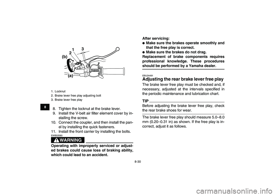
8. Tighten the locknut at the brake lever.
9. Install the V-belt air filter element cover by in-
stalling the screw.
10. Connect the coupler, and then install the pan-
el by installing the quick fasteners.
11. Install the front carrier by installing the bolts.
WARNING
EWB02080
Operating with improperly serviced or adjust-
ed brakes could cause loss of braking ability,
which could lead to an accident.After servicing:
�
Make sure the brakes operate smoothly and
that the free play is correct.
�
Make sure the brakes do not drag.
Replacement of brake components requires
professional knowledge. These procedures
should be performed by a Yamaha dealer.
EBU24491
Adjusting the rear brake lever free play
The brake lever free play must be checked and, if
necessary, adjusted at the intervals specified in
the periodic maintenance and lubrication chart.
TIP
Before adjusting the brake lever free play, check
the rear brake shoes for wear.
The brake lever free play should measure 5.0–8.0
mm (0.20–0.31 in) as shown. If the free play is in-
correct, adjust it as follows.
1. Locknut
2. Brake lever free play adjusting bolt
3. Brake lever free play
3
1
2
(b)
(a)
Page 121 of 130

10-2
1
2
3
4
5
6
7
8
910
11
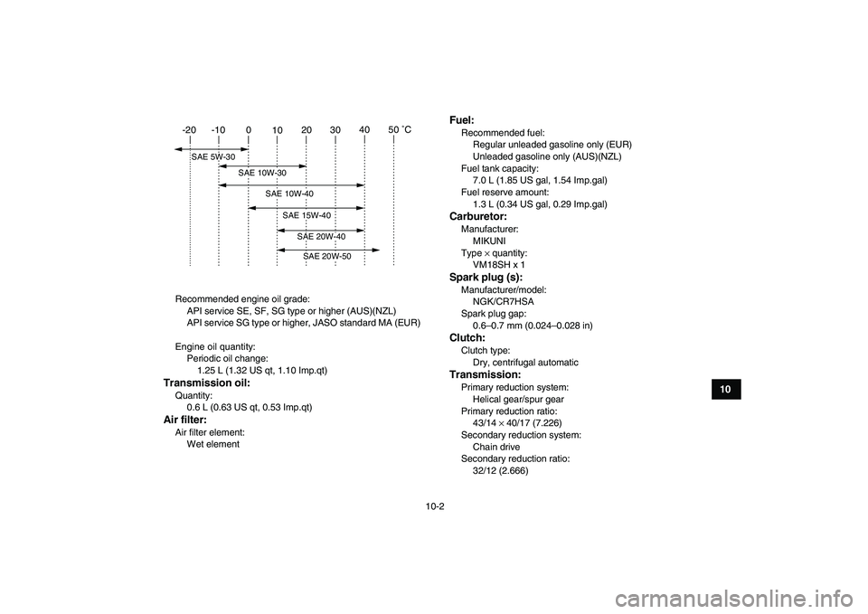
Recommended engine oil grade:
API service SE, SF, SG type or higher (AUS)(NZL)
API service SG type or higher, JASO standard MA (EUR)
Engine oil quantity:
Periodic oil change:
1.25 L (1.32 US qt, 1.10 Imp.qt)
Transmission oil:
Quantity:
0.6 L (0.63 US qt, 0.53 Imp.qt)
Air filter:
Air filter element:
Wet element
Fuel:
Recommended fuel:
Regular unleaded gasoline only (EUR)
Unleaded gasoline only (AUS)(NZL)
Fuel tank capacity:
7.0 L (1.85 US gal, 1.54 Imp.gal)
Fuel reserve amount:
1.3 L (0.34 US gal, 0.29 Imp.gal)
Carburetor:
Manufacturer:
MIKUNI
Type
×
quantity:
VM18SH x 1
Spark plug (s):
Manufacturer/model:
NGK/CR7HSA
Spark plug gap:
0.6–0.7 mm (0.024–0.028 in)
Clutch:
Clutch type:
Dry, centrifugal automatic
Transmission:
Primary reduction system:
Helical gear/spur gear
Primary reduction ratio:
43/14
×
40/17 (7.226)
Secondary reduction system:
Chain drive
Secondary reduction ratio:
32/12 (2.666)
-20 -10 0
1020 304050 ˚C
SAE 15W-40
SAE 20W-40SAE 20W-50
SAE 10W-40
SAE 5W-30
SAE 10W-30
Page 127 of 130

INDEX
A
Accessories and loading ................................................ 6-6
Air filter elements, engine and V-belt filter cleaning ..... 8-15
B
Battery .................................................................. 5-6
,
8-38
Brake lever free play, adjusting the front...................... 8-25
Brake lever free play (rear), adjusting .......................... 8-30
Brake lever, front ............................................................ 4-4
Brake lever, rear............................................................. 4-4
Brake levers, checking and lubricating......................... 8-36
Brakes, front and rear .................................................... 5-3
Brake shoes, checking the front and rear .................... 8-24
C
Cables, checking and lubricating ................................. 8-35
Carburetor, adjusting.................................................... 8-22
Carrier, front ................................................................. 4-10
Carrier, rear .................................................................. 4-10
Chassis fasteners........................................................... 5-6
Cleaning ......................................................................... 9-1
D
Drive chain ..................................................................... 5-4
Drive chain, lubricating ................................................. 8-34
Drive chain slack .......................................................... 8-32
Drive select lever............................................................ 4-6
Drive select lever and driving in reverse ........................ 6-3
E
Engine break-in .............................................................. 6-4
Engine, cold start ........................................................... 6-1
Engine idling speed ...................................................... 8-22
Engine oil ............................................................... 5-3
,
8-9
Engine, starting a warm ................................................. 6-3
Engine stop switch ......................................................... 4-2
F
Front knuckle pivots, lubricating ................................... 8-37
Fuel ........................................................................ 4-6
,
5-3
Fuel cock ........................................................................ 4-7
Fuel tank cap.................................................................. 4-6
Fuse, replacing............................................................. 8-41
H
Handlebar switches ........................................................ 4-2
Headlight beam, adjusting............................................ 8-44
Headlight bulb, replacing.............................................. 8-42
I
Identification numbers .................................................. 11-1
Indicator lights ................................................................ 4-1
Instruments, lights and switches .................................... 5-6
K
Key identification number ............................................. 11-1
L
Label locations ............................................................... 2-1
Light switch .................................................................... 4-2