Page 57 of 104

PERIODIC MAINTENANCE AND ADJUSTMENT
6-8
6 To install the panel
Place the panel in the original position,
and then install the screw.FZ1-S
FZ1-SA
EAU19652
Checking the spark plugs The spark plugs are important engine
components, which should be checked
periodically, preferably by a Yamaha
dealer. Since heat and deposits will
cause any spark plug to slowly erode,
they should be removed and checked
in accordance with the periodic mainte-
nance and lubrication chart. In addition,
the condition of the spark plugs can re-
veal the condition of the engine.
The porcelain insulator around the cen-
ter electrode of each spark plug should
be a medium-to-light tan (the ideal color
when the vehicle is ridden normally),
and all spark plugs installed in the en-
gine should have the same color. If any
spark plug shows a distinctly different
color, the engine could be operating im-
properly. Do not attempt to diagnose
such problems yourself. Instead, have
a Yamaha dealer check the vehicle.
If a spark plug shows signs of electrode
erosion and excessive carbon or other
deposits, it should be replaced.
1. Panel C
2. Screw
Specified spark plug:
NGK/CR9EK
U3C3E3E0.book Page 8 Thursday, July 10, 2008 2:03 PM
Page 58 of 104

PERIODIC MAINTENANCE AND ADJUSTMENT
6-9
6Before installing a spark plug, the spark
plug gap should be measured with a
wire thickness gauge and, if necessary,
adjusted to specification.
Clean the surface of the spark plug
gasket and its mating surface, and then
wipe off any grime from the spark plug
threads.
TIPIf a torque wrench is not available when
installing a spark plug, a good estimate
of the correct torque is 1/4–1/2 turn
past finger tight. However, the spark
plug should be tightened to the speci-fied torque as soon as possible.NOTICE
ECA10840
Do not use any tools to remove or in-
stall the spark plug cap, otherwise
the ignition coil coupler may get
damaged. The spark plug cap may
be difficult to remove because the
rubber seal on the end of the cap fits
tightly. To remove the spark plug
cap, simply twist it back and forth
while pulling it out; to install it, twistit back and forth while pushing it in.
EAU19876
Engine oil and oil filter car-
tridge The engine oil level should be checked
before each ride. In addition, the oil
must be changed and the oil filter car-
tridge replaced at the intervals speci-
fied in the periodic maintenance and
lubrication chart.
To check the engine oil level
1. Place the vehicle on the center-
stand. A slight tilt to the side can
result in a false reading.
2. Start the engine, warm it up for
several minutes, and then turn it
off.
3. Wait a few minutes until the oil set-
tles, and then check the oil level
through the engine oil level check
window located at the bottom-right
side of the crankcase.TIPThe engine oil should be between theminimum and maximum level marks.
1. Spark plug gapSpark plug gap:
0.6–0.7 mm (0.024–0.028 in)
Tightening torque:
Spark plug:
12.5 Nm (1.25 m·kgf, 9.0 ft·lbf)
U3C3E3E0.book Page 9 Thursday, July 10, 2008 2:03 PM
Page 59 of 104

PERIODIC MAINTENANCE AND ADJUSTMENT
6-10
6 4. If the engine oil is below the mini-
mum level mark, add sufficient oil
of the recommended type to raise
it to the correct level.
To change the engine oil (with or
without oil filter cartridge replace-
ment)
1. Place the vehicle on a level sur-
face.
2. Start the engine, warm it up for
several minutes, and then turn it
off.
3. Place an oil pan under the engine
to collect the used oil.4. Remove the engine oil filler cap
and drain bolt to drain the oil from
the crankcase.
TIPSkip steps 5–7 if the oil filter cartridge isnot being replaced.
5. Remove the oil filter cartridge with
an oil filter wrench.
TIPAn oil filter wrench is available at aYamaha dealer.
6. Apply a thin coat of clean engine
oil to the O-ring of the new oil filter
cartridge.
1. Engine oil filler cap
2. Engine oil level check window
3. Maximum level mark
4. Minimum level mark
1. Engine oil drain bolt
1. Oil filter wrench
2. Oil filter cartridge
U3C3E3E0.book Page 10 Thursday, July 10, 2008 2:03 PM
Page 60 of 104

PERIODIC MAINTENANCE AND ADJUSTMENT
6-11
6
TIPMake sure that the O-ring is properlyseated.
7. Install the new oil filter cartridge
with an oil filter wrench, and then
tighten it to the specified torque
with a torque wrench.8. Install the engine oil drain bolt, and
then tighten it to the specified
torque.
9. Refill with the specified amount of
the recommended engine oil, and
then install and tighten the oil filler
cap.
TIPBe sure to wipe off spilled oil on any
parts after the engine and exhaust sys-tem have cooled down.NOTICE
ECA11620
�
In order to prevent clutch slip-
page (since the engine oil also
lubricates the clutch), do not
mix any chemical additives. Do
not use oils with a diesel speci-
fication of “CD” or oils of a high-
er quality than specified. In
addition, do not use oils labeled
“ENERGY CONSERVING II” or
higher.
�
Make sure that no foreign mate-rial enters the crankcase.
1. O-ring
1. Torque wrenchTightening torque:
Oil filter cartridge:
17 Nm (1.7 m·kgf, 12 ft·lbf)
Tightening torque:
Engine oil drain bolt:
43 Nm (4.3 m·kgf, 31 ft·lbf)
Recommended engine oil:
See page 8-1.
Oil quantity:
Without oil filter cartridge replace-
ment:
2.90 L (3.07 US qt, 2.55 Imp.qt)
With oil filter cartridge replacement:
3.10 L (3.28 US qt, 2.73 Imp.qt)
U3C3E3E0.book Page 11 Thursday, July 10, 2008 2:03 PM
Page 61 of 104

PERIODIC MAINTENANCE AND ADJUSTMENT
6-12
6 10. Start the engine, and then let it idle
for several minutes while checking
it for oil leakage. If oil is leaking, im-
mediately turn the engine off and
check for the cause.
TIPAfter the engine is started, the engine
oil level warning light should go off if theoil level is sufficient.NOTICE
ECA10400
If the oil level warning light flickers
or remains on, immediately turn the
engine off and have a Yamaha dealercheck the vehicle.11. Turn the engine off, and then
check the oil level and correct it if
necessary.
EAU20070
Coolant The coolant level should be checked
before each ride. In addition, the cool-
ant must be changed at the intervals
specified in the periodic maintenance
and lubrication chart.
EAU40042
To check the coolant level
1. Place the vehicle on the center-
stand.TIP�
The coolant level must be checked
on a cold engine since the level
varies with engine temperature.
�
Make sure that the vehicle is posi-
tioned straight up when checking
the coolant level. A slight tilt to the
side can result in an incorrectreading.
2. Check the coolant level in the cool-
ant reservoir.
TIPThe coolant should be between theminimum and maximum level marks.
1.“CD” specification
2.“ENERGY CONSERVING II”
1
2
U3C3E3E0.book Page 12 Thursday, July 10, 2008 2:03 PM
Page 62 of 104

4. Remove the reservoir cap, add
coolant to the maximum level
mark,")
PERIODIC MAINTENANCE AND ADJUSTMENT
6-13
63. If the coolant is at or below the
minimum level mark, remove pan-
el C. (See page 6-7.)
4. Remove the reservoir cap, add
coolant to the maximum level
mark, and then install the reservoir
cap. WARNING! Remove only
the coolant reservoir cap. Never
attempt to remove the radiator
cap when the engine is hot.
[EWA15161]
NOTICE: If coolant is not
available, use distilled water or
soft tap water instead. Do not
use hard water or salt water
since it is harmful to the engine.
If water has been used insteadof coolant, replace it with cool-
ant as soon as possible, other-
wise the cooling system will not
be protected against frost and
corrosion. If water has been
added to the coolant, have a
Yamaha dealer check the anti-
freeze content of the coolant as
soon as possible, otherwise the
effectiveness of the coolant will
be reduced.
[ECA10472]
5. Install the panel.
EAU33031
Changing the coolant
The coolant must be changed at the in-
tervals specified in the periodic mainte-
nance and lubrication chart. Have a
Yamaha dealer change the coolant.
WARNING! Never attempt to remove
the radiator cap when the engine is
hot.
[EWA10381]
1. Coolant reservoir
2. Maximum level mark
3. Minimum level mark
1. Coolant reservoir capCoolant reservoir capacity (up to the
maximum level mark):
0.25 L (0.26 US qt, 0.22 Imp.qt)
U3C3E3E0.book Page 13 Thursday, July 10, 2008 2:03 PM
Page 63 of 104

PERIODIC MAINTENANCE AND ADJUSTMENT
6-14
6
EAU40053
Replacing the air filter element The air filter element should be re-
placed at the intervals specified in the
periodic maintenance and lubrication
chart. Replace the air filter element
more frequently if you are riding in un-
usually wet or dusty areas.
1. Remove the rider seat. (See page
3-19.)
2. Remove panels A and B. (See
page 6-7.)
3. Remove the cowling bolts, and
then pull the cowling off.
4. Remove the fuel tank bolts.5. Lift the front of the fuel tank, and
carefully tilt it back and away from
the air filter case, but do not dis-
connect the fuel hoses.
WARNING! Make sure that the
fuel tank is well supported. Do
not tilt or pull the fuel tank too
much, otherwise the fuel hoses
may come loose, which could
cause fuel leakage and a fire
hazard.
[EWA10411]
6. Remove the air filter case cover by
removing the screws. NOTICE:
When removing the air filter
case cover, be careful not to al-
low foreign objects to drop into
the air intake manifold.
[ECA12881]
7. Pull the air filter element out.
1. Cowling
2. Bolt
1. Bolt
1. Screw
2. Air filter case cover
U3C3E3E0.book Page 14 Thursday, July 10, 2008 2:03 PM
Page 64 of 104

PERIODIC MAINTENANCE AND ADJUSTMENT
6-15
68. Insert a new air filter element into
the air filter case. NOTICE: Make
sure that the air filter element is
properly seated in the air filter
case. The engine should never
be operated without the air filter
element installed, otherwise the
piston(s) and/or cylinder(s) may
become excessively worn.
[ECA10481]
9. Install the air filter case cover by in-
stalling the screws.
10. Place the fuel tank in the original
position. Make sure that the fuel
hoses are properly connected and
routed, and not pinched. Be sure
to place the fuel tank breatherhose and the fuel tank overflow
hose in the original position.
WARNING! Before placing the
fuel tank in the original position,
make sure that the fuel hoses
are not damaged. If any fuel
hose is damaged, do not start
the engine but have a Yamaha
dealer replace the hose, other-
wise fuel may leak, creating a
fire hazard.
[EWA11361]
FZ1-SFZ1-SA
FZ1-SA
11. Install the fuel tank bolts.
12. Place the cowling in the original
position, and then install the bolts.
13. Install the panels.
1. Air filter element
2. Air intake manifold
1. Fuel tank breather hose
2. Original position (paint mark)
3. Fuel tank overflow hose
3
1. Fuel tank overflow hose
2. Original position (paint mark)
1. Fuel tank breather hose
2. Original position (paint mark)
12
U3C3E3E0.book Page 15 Thursday, July 10, 2008 2:03 PM
 1
1 2
2 3
3 4
4 5
5 6
6 7
7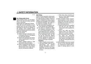 8
8 9
9 10
10 11
11 12
12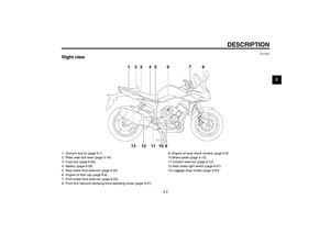 13
13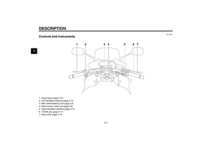 14
14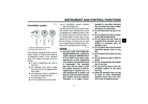 15
15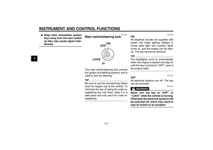 16
16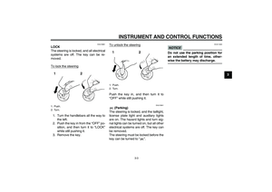 17
17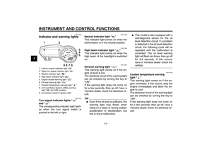 18
18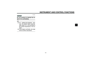 19
19 20
20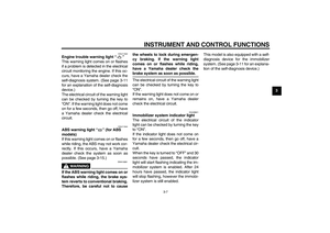 21
21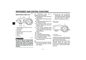 22
22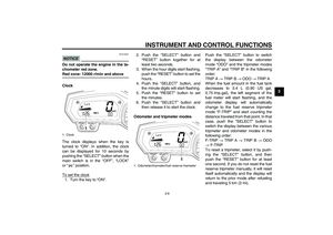 23
23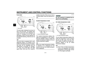 24
24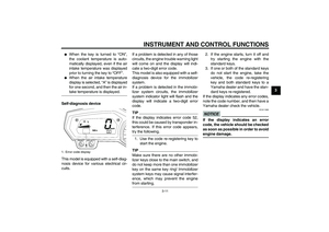 25
25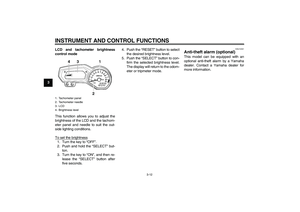 26
26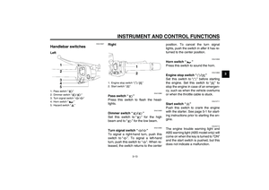 27
27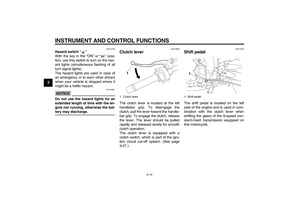 28
28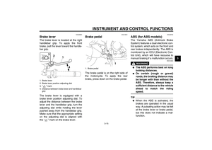 29
29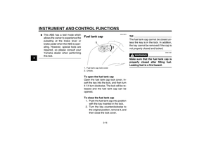 30
30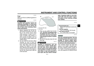 31
31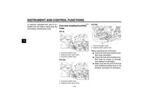 32
32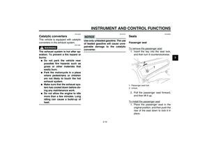 33
33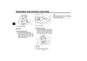 34
34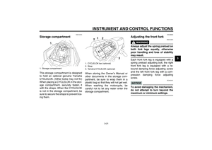 35
35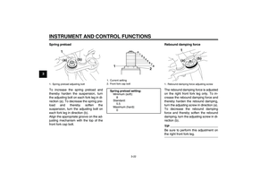 36
36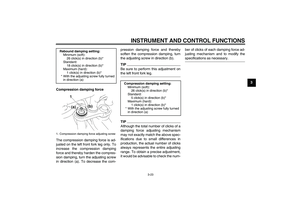 37
37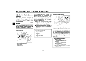 38
38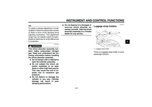 39
39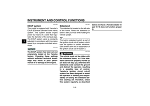 40
40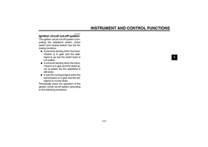 41
41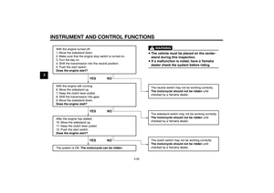 42
42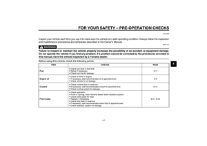 43
43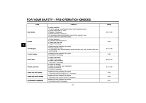 44
44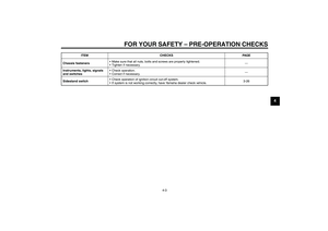 45
45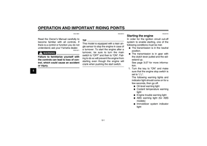 46
46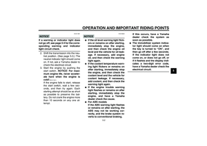 47
47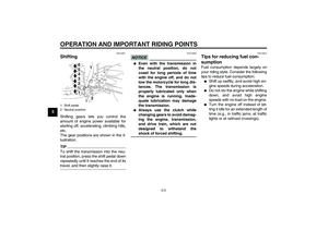 48
48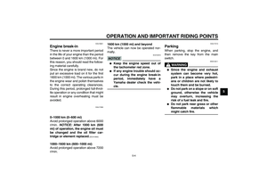 49
49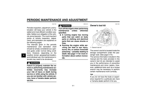 50
50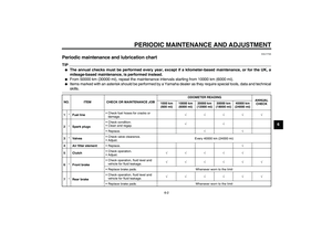 51
51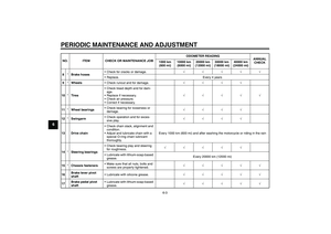 52
52 53
53 54
54 55
55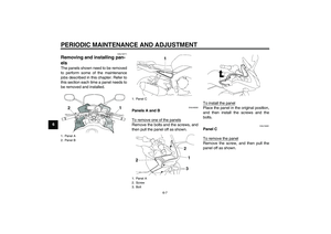 56
56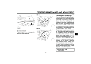 57
57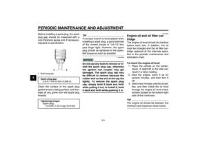 58
58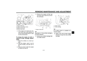 59
59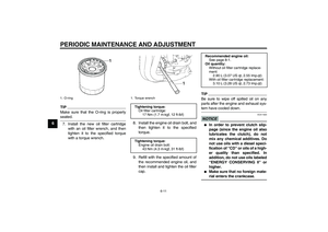 60
60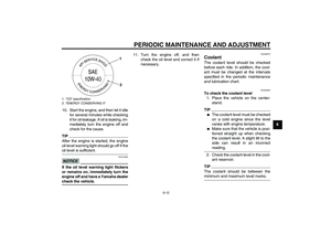 61
61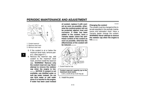 62
62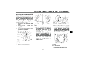 63
63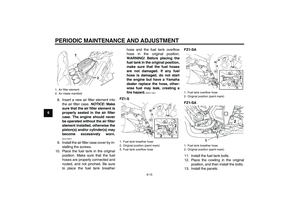 64
64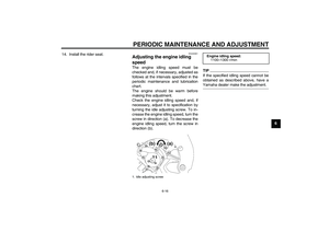 65
65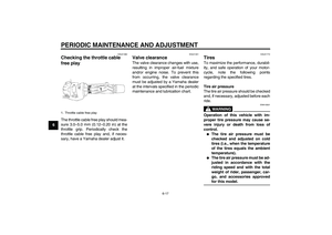 66
66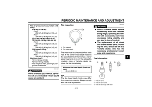 67
67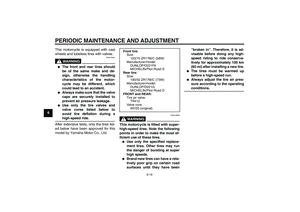 68
68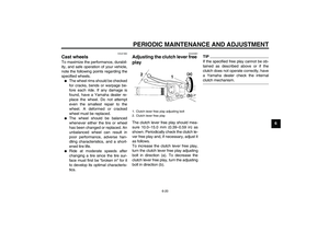 69
69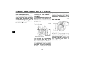 70
70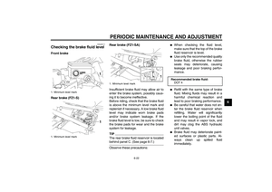 71
71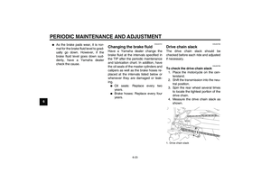 72
72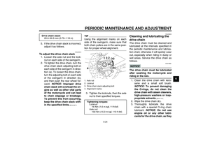 73
73 74
74 75
75 76
76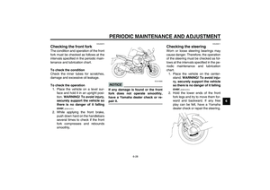 77
77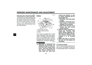 78
78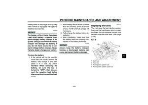 79
79 80
80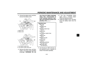 81
81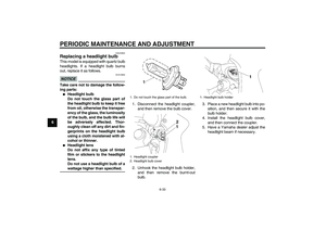 82
82 83
83 84
84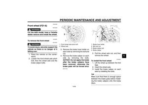 85
85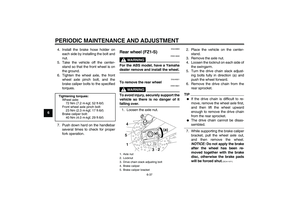 86
86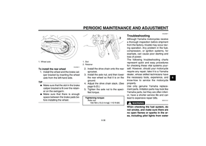 87
87 88
88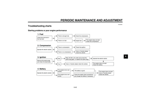 89
89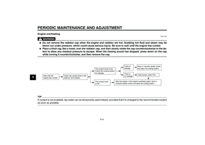 90
90 91
91 92
92 93
93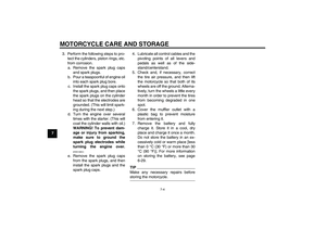 94
94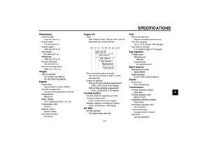 95
95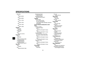 96
96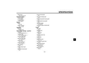 97
97 98
98 99
99 100
100 101
101 102
102 103
103