2009 VOLKSWAGEN SCIROCCO tow
[x] Cancel search: towPage 72 of 138
Downloaded from www.Manualslib.com manuals search engine . -~~~Q§@~~iC!~;a--................................................................ ~~~~--~--~~~~.a.-.. __ .... ~.c .. ~~~~ ~ .. ~h:;;;;;;..,-~= I n 70 a M= ,..._ ~;e,--~· ... - - -v· --.. iiA.ir ...
...
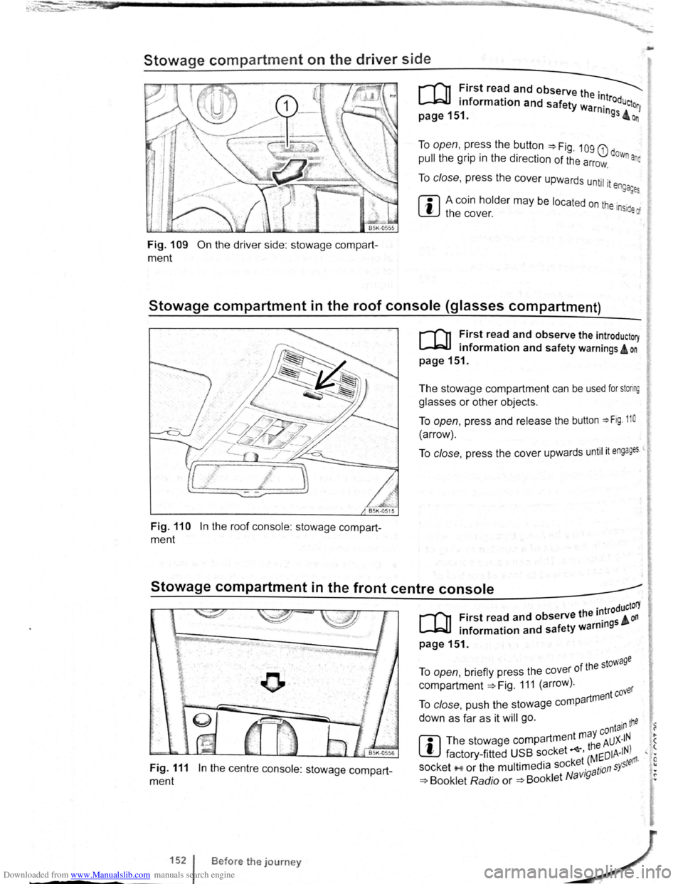
Stowage compartment on the driver side
Fig. 109 On the driver side: stowage compart
ment
To open, press the button ~Fig. 109 G) dow .
pull the grip in the direction of the arrow. n ana
To close, press the cover upwards until it e ngages
ffi A coin holder may be located on the inside of W the cover.
Stowage compartment in the roof console (glasses compartment)
Fig. 110 In the roof console : stowage compart
ment
r-('n First read and observe the introductory
~ information and safety warnings A on
page 151.
The stowage compartment can be used for storing
glasses or other objects.
To open, press and release the button ~Fig. 110
(arrow).
To close, press the cover upwards until it engages <
Stowage compartment in the front centre console _____.
Fig. 111 In the centre console: stowage compart
ment
1521
-----
B efore the journey
. troductorY
[Q] First read and observe the 1~ 5 & on . f ty warnm9 • information and sa e
page151.
f the stowage To open, briefly press the cover 0
compartment ~Fig. 111 (arrow). ver
artment eo To close, push the stowage comp
down as far as it will go. ·n tne • -y conta1 1 ?
rn
The stowage compartment m a AUX-IN . ( ~ th8 ' t factory -fitted USB socket ' Mr:DIA-IN) , • · ket ( ~ tefl'l· E socket '"'' or the multimedia soc ·g a tion s Y5
, •
~ Booklet Radio or ~Booklet N avt • ~
Page 73 of 138
Downloaded from www.Manualslib.com manuals search engine ~
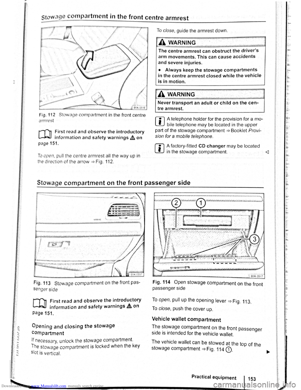
cornp~rtment in the front centre armrest
r-('n First read and observe the introductory
l.-J,r::JJ information and safety warnings th on
png 151.
li pen, pu ll the ce ntre armres t all the way up in
tt e 1re ti n o f the arrow ::. Fig . 112 .
To clo se, guide the a rmr est down .
A WARNING
The centre armrest can obstruct the driver's
arm movements. This can cause accidents
and severe injuries.
• Always keep the stowage compartments
in the centre armrest closed while the vehicle
is in motion.
Never transport an adult or child on the cen
tre armrest.
m A telephone holder for the provision for a mo
L!J bile telephone may be located in the upper
part of the stowage compartment ::.Bookl et Pro vi
sion for a mobile telephone .
m A factory-fi tted CD changer may be located
W in the stowage compartment.
Stowage compartment on the front passenger side
Fig . 113 St wage compartment on the front pas
en er si e
,.....-('n First read and observe the introductory
~ information and safety warnings.&. on
page 151 .
Opening and closing the stowage
compartment
If n es ary, unlock the stowage compartment.
T e
to~ age compartm ent is locked when the key
t is ert ical.
Fig. 114 Open stowage compartment on the front
passenger side
To open, pull up the opening lever ::. Fig. 113.
To close , push the cover up.
Vehicle wallet compartment
T.he ~~~wage compartment on the front passenger
s1de IS mtended for the vehicle wallet.
The vehicle wallet can be stowed at the top of the
stowage compartment
==>Fig. 114 G).
Practical equipment 153
~--------------------~~----------~--~.~! ~--.J-------~
I ,.
~·
~
I
t
r
r r I.
t·
'
Page 77 of 138
Downloaded from www.Manualslib.com manuals search engine rfl If tho lo vo r Is move d accid entally to N when
L!J dr iving , take yo ur foot off the accele rato r.
WiJil fo r tile e ng in e ~~v s in t~e ne utral po sitio n be-
fo re solo ctin g a pos1!1o n agam.
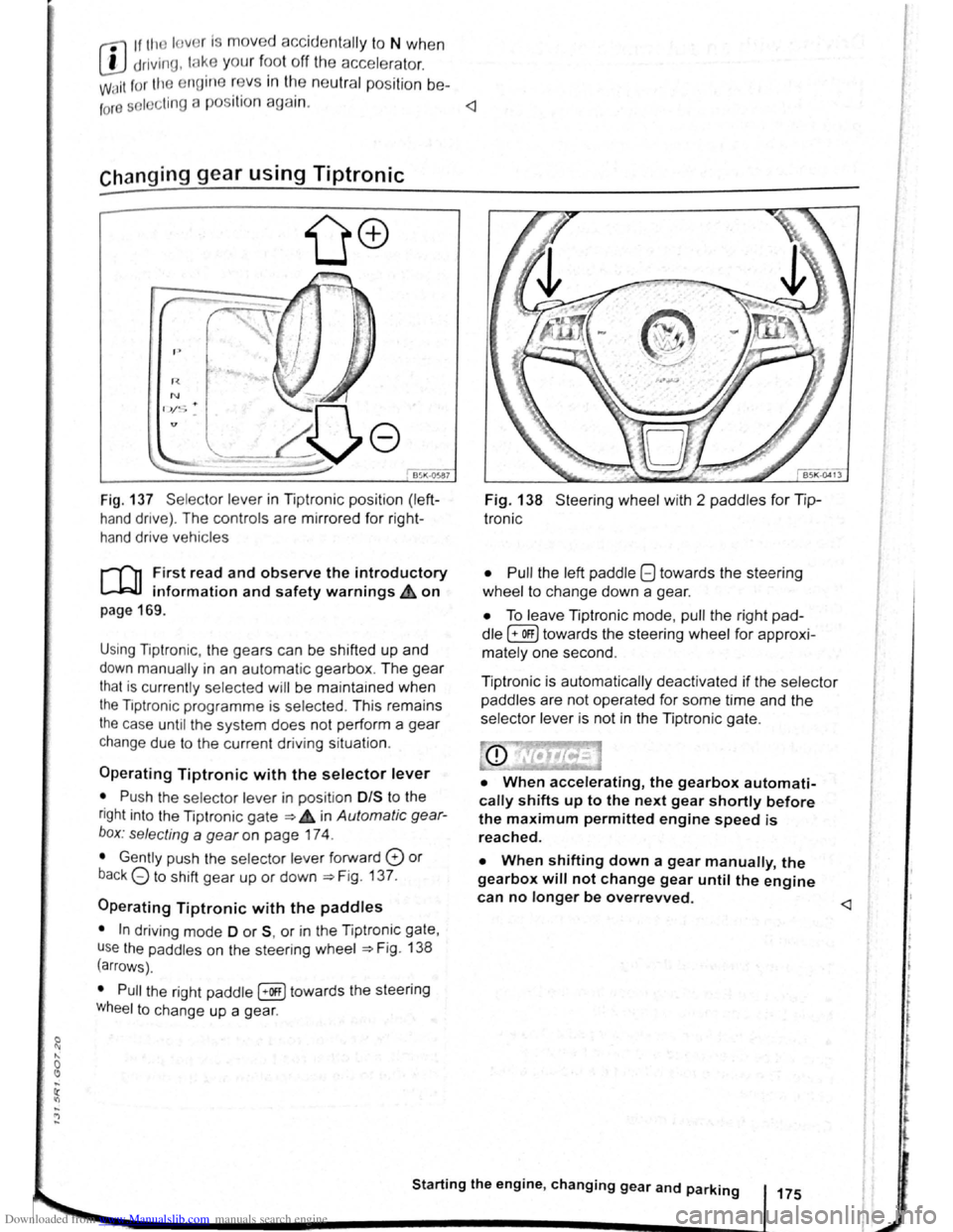
Fig. 137 Se lecto r leve r in Tiptronic position (left
hand drive) . The controls are mirrored for right
hand drive vehicles
rT'n F irst read and observe the introductory
L-.W.I information and safety warnings.& on
page 169 .
Using Tiptronic , the ge ars can be shifted up and
down manually in an automat ic gearbox . The gear
that is currently selected will be maintained when
the Tiptronic programme is selected . This remains
the case until the system does not perform a gear
change due to the current driv ing situation .
Operating Tiptronic with the selector lever
• Push the selector lever in pos it ion 0/S t o the
right into the Tiptronic gate ~ 4 in Automatic gear
b o x: selecting a
gear on page 174 .
• Gently push the selecto r lever forward 0 or
back G to shift gear up or down ~Fig. 137.
Operating Tiptronic with the paddles
• In driving mode 0 or S, or in the Tiptronic gate,
u se
the paddles o n the steering wheel ~Fig. 138
(arrows) .
• Pull the right paddle [+Off] towards the steering
Wheel to change up a gea r.
Fig. 138 Steer ing wheel with 2 padd les for Tip
Ironic
• Pull
the left paddle 8 towards the stee ring
whe el to cha nge down a gea r.
• To leave Tiptronic mode, pull the right pad
dle (+OFF) towa rds the steering whee l for approxi
mat ely one second .
Tiptronic is
automatically deactivated if the selector
paddles
are not operated for some time and the
selector lever is not in the Tiptronic gate.
• When accelerating, the gearbox automati
cally shifts up to the next gear shortly before
the maximum permitted engine speed is
reached.
• When shifting down a gear manually, the
gearbox will not change gear until the engine
can no longer be overrevved.
l t t
t
r
Page 78 of 138
Downloaded from www.Manualslib.com manuals search engine riving with an automatic gearbox
r-T'n First read and observe t h e introductory
L-..kJJ information and safety warnings~ on
page 169.
The gearbox changes th e forwa rd gears up and
down automat ic a lly .
Driving down hills
The steeper the gradi ent, the lower the gear you
will need . Lower gears increase the braking effect
of the engine . Never allow the vehicle to roll down
mountains or hills in the neutral position N.
• Reduce your speed.
• Push the selector lever from posit ion D t o the
r i
ght into the Tiptron ic gate ~page 175.
• Gently push the selector le ver to the rear to
change down gear.
• OR: shift down a gear using the padd les on the
s te
erin g wheel ~page 175 .
Stopping the vehicle and pulling away when
driving uphill
The steeper the incline, the lower the gear you will
need.
If you wish to stop the vehic le or pu ll away when
driv ing uphill you should use the Auto -Ho
ld func
tion
~page 196.
When you stop the vehicle on an incl ine and the
vehicle remains in gear , the vehicle must always
be prevented fro m rolling by depress ing the brake
pedal or
by applying the electron ic park ing brake .
The brake pedal or the electronic parking brake
should
not be released until you pull away ~CD.
Freewheel driving with dual clutch gearbox
DSG®
In
freewheel mode, the momentum of the vehicle is
used to save fuel with a foresighted driving style.
The engine is declutched and no longer brakes the
vehicle -the vehicle can
roll out over a longer dis
t a nce.
Switch-on condit io n: the selector lever must be in
positio n D.
Triggering freewheel driving
• Select the Eco driving mode from the Driving
Mode Selection menu ~page 248 .
• Remove foot from accelerator pedal. The en
gine
w ill be disengaged and run in freewheel
mode. The vehicle rolls without the braking effect
of the eng ine .
Cancelling freewheel mode
• Press the bra e pedal brieny or pull the 1 ft.
hand paddle G towards the stee ring wh 1.
Kick-down
The kickdown function enab~~s ma imum accelera.
tion in the selec tor lever pos1t1ons D and S, or in
th e Tiptron ic posi tio n.
If the acce lerator pedal is d epre ssed fully. the gear.
box will automat ically sh ift to a lower gear, depend
ing on the speed and engine revs. This will make
use of the full veh icle acceleration ~ Lt.
The gearbox does not shift up to the next gear until
the engine reaches the maximum engine s
peed for
the gear.
When the
Eco driving mode is sel ected in vehicles
with Driving Mode Selection ~page 248 and the
accelerator is depressed
fully beyond the pressure
point, the engine output is automatically regulated
to ensure maximum vehicl e acceleration .
Launch control programme
The launch control programme enables maximum
accelerat ion from a stand ing start .
• Switch off TCS ~page 179.
• Depress and hold the brake pedal with your left
foot.
• Move the selector lever to position S, or into the
Tiptronic position. Alte rnatively , select the Sport
driving mode in vehi cles with Driv ing Mode Selec
tion ~page 248 .
• With your right foot, depress the accelerator un
til the engines speed reaches approximately
3,200 rpm.
• Take your left foot off the brake ~ ~. The vehi
cle will start with maximum acceleration.
• Switch the TCS back on after accelerat ion.
A WARNING
Rapid acceleration can cause loss of traction
and skidding, particularly on slippery roads .
This can cause you to lose control of the ~e
hicle, which can lead to accidents and sen·
ous injuries.
• Always adjust your driving style in ac·
cordance with the flow of traffic.
• Only use kickdown or fast acceleration if
visibility, weather road and traffic conditions ' t permit, and other road users are not put a
risk due to the acceleration and the driving
style.
,
Page 80 of 138
Downloaded from www.Manualslib.com manuals search engine Gear-change indicator
B~K-O~Y8
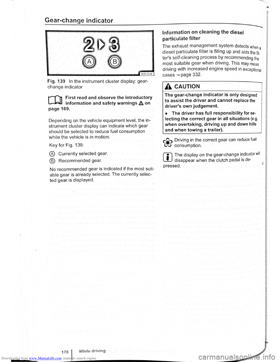
Fig. 139 In the instrument cluster display: gear
change indicator
r-T'n First read and observe the introductory
L-.WI information and safety warnings ~ on
page 169.
D epending on the vehicle equipment
level, the in
strument cluster display can indicate which gear
should be selected to reduce fuel consumption
while the vehicle is in motion :
Key for Fig. 139:
® Currently selected gear.
@ Recommended gear.
No recommended gear is indicated if the most suit
able gear is already selected . The currently selec
ted gear is displayed .
178 While driving
Information on cleaning the diesel
particulate
filter
The exhaust management system detects whe
diesel particulate filter is filling up and aids the ~l-a
ter's self-cleaning process by recommending the
most suitable gear when driving . This may mean
driving with increased engine speed in exceptional
cases
=>page 332 .
A CAUTION
The gear-change indicator is only designed
to assist the driver and cannot replace the
driver's own judgement.
• The driver has full responsibility for se
lecting the correct gear in all situations (e.g .
when overtaking, driving up and down hills
and when towing a trailer).
r::Gb Driv ing in the correct gear can reduce fuel
W consumpt ion.
m The display on the gear-change indicator will
W disappear when the clutch pedal is de·
pressed . 4
•
Page 84 of 138
Downloaded from www.Manualslib.com manuals search engine ~S~ta~~~st~o~p~s~y~s~te~m~--------------------------------------
BSG-0005
Fig. 146 In the centre consol e: butt on for the
s tart/s top syst em
r-T'n First read and observe the introductory
L-lcJJ information and safety warnings .&. on
page
196.
The start/stop system automatically switches the
engine off when the vehicle is stationary . When re
quired , the engine restarts automatically .
The function is automatically activated every time
the ignit ion is switched on. The instrument cluster
display will show information about the current sta
tus .
You can find additional information on the start/
stop mode by pressing
the~ button in the Vehi
cl e status menu in the infota inment system .
Always deactivate the start/stop system manually
when driving through water.
Vehicles with a manual gearbox
• When the vehicle is stat ionary , d isengage the
g e
ar and release the clutch pedal. The engine is
stopped .
• Depress the clutch pedal to restart the engine .
Vehicles with an automatic gearbox
• When the vehicle is stationary , press and hold
the brake pedal. The engine
is stopped.
• Ta ke your foot off the brake pedal, or depress
the acce lerator, to restart the engine .
Important preconditions for automatic
engine switch-off
• The driv er is wearing their seat belt.
• The driver door is closed .
• The bonnet is closed .
• The factory-fitted towing bracket is not attached
ele ctrically to a trailer .
• A minimum engine temperature has been
rea ched .
198 I While driving
• The ve hicle has been moved since the engine
was las t switc he d off.
• F or v ehicle s with Climatronic: the temperatu
inside the ve hicle is within the pre-set temperat~~e
ra nge .
• The de frost function of the air conditioning sys.
tem is not switched on.
• The charging state of the vehicle battery is suf.
ficient.
• The temperature of the vehicle battery is not
too
low or too high .
• The vehicle is not on a steep incline.
• For vehicles with an automatic gearbox: the
front wheels are not angled too sharply .
• The windscreen heating is not switched on.
• Reverse gear is not engaged .
• The park assist system (Park Assist) system is
not active .
When the condit ions
for automatic engine swit ch
off are only fulfilled when the vehicle is stationary,
the engine can also switch off subsequently :
• When the driver creates the required conditions
by performing an action , e .g . by switching off the
defrost function .
• If the @ button in the centre console is pressed
twice ~Fig. 146.
• When selector lever position P is selected in
vehicles with an automatic gearbox.
Conditions for an automatic restart
The engine can start automatically under the fol
lowing conditions :
• If the temperature inside the vehicle substan
tially increases or decreases .
• If the vehicle rolls on.
• If the voltage of the vehicle battery falls.
• If the steering wheel is moved.
Conditions that require a manual engine
start
The engine must be started manually in the folloW·
ing conditions :
• If the driver unfastens their seat belt.
• If the driver door is opened .
• If the bonnet is opened.
Page 86 of 138

Downloaded from www.Manualslib.com manuals search engine -•
parkPilot
COl Introduction
This chapter contains information on the following
subjects:
Operating ParkPilot . . . . . . . . . . . . . . . . . . . . . . 202
parkPilot display
. . . . . . . . . . . . . . . . . . . . . . . . 204
ParkPilot menu . . . . . . . . . . . . . . . . . . . . . . . . . 206
Vehicle path display . . . . . . . . . . . . . . . . . . . . . 207
Towing a trailer . . . . . . . . . . . . . . . . . . . . . . . . . . 208
The ParkPilot assists the driver when manoeuvring
and parking . If the vehicle is approaching an obsta
cle located in the range of the ultrasound sensors ,
an intermittent acoustic warning is sounded , de
pending on the distance . The shorter the distance ,
the shorter the intervals . The acoustic warning will
sound continuously if the obstacle is very close .
The ultrasound sensors in the bumpers transmit
and receive ultrasound waves. The system uses
the time difference between the ultrason ic waves
(i.e. between the transmission and reflection from
obstacles and the point of reception) to continu
ously calculate the distance between the bumper
and the obstacle.
Additional information and warnings:
• Exterior views ~page 6
• lnfotainment system ~page 31
• Braking , stopping and parking ~page 179
• Reverse assist system (Rear Assist)
~page 209
• Park
assist system (Park Assist) ~page 213
• Cleaning and caring for the vehicle exterior
~page 294
• Accessories , modificat ions , repairs and renewal
of parts ~page 320
A WARNING
The ParkPilot cannot replace the full concen
tration of the driver.
• Unintentional vehicle movements can
cause serious injury.
• Always adapt your speed and driving style
to suit visibility, weather, road and traffic con
ditions.
• Ultrasound sensors have blind spots in
Which obstacles and people cannot be detec
ted '--.
A WARNING (Continued) ~-
• Always monitor the area around the vehi
cle as the ultrasound sensors will not always
detect infants, animals and objects.
• Certain surfaces of objects and clothes
cannot reflect the signals from the ultrasound
sensors. The system is unable to detect
these objects or people wearing this type of
clothing, or they may be detected incorrectly.
• External sources of sound can affect the
signals of the ultrasound sensors. In certain
circumstances, the system may not recog
nise people or objects.
A WARNING ~-.
Automatic activation of the ParkPilot only oc
curs at very low speeds. An inappropriate
driving style can cause accidents and serious
injuries.
• Always bear in mind the time delay be
tween the signals.
• The ultrasound sensors may not always be
able to detect objects such as trailer drawbars,
thin rails, fences, posts, trees and open or
opening tailgates. This can result in damage to
your vehicle.
• If the ParkPilot has detected an obstacle
and issued a warning, the obstacle may move
out of the detection range of the sensors as the
vehicle approaches it, particularly if the object
is very high or very low. These objects are no
longer registered.
• The vehicle can sustain considerable dam
age if the warning given by the ParkPilot is ig
nored.
• The ultrasound sensors in the bumper can
be displaced or damaged through impacts, e.g.
when parking.
• The ultrasound sensors in the bumpers
must be kept clean and free of ice and snow
and not be covered up by stickers or other
items, as these may prevent the system from
working properly.
Driver assist systems 2o1
Page 89 of 138
Downloaded from www.Manualslib.com manuals search engine ParkPilot di play
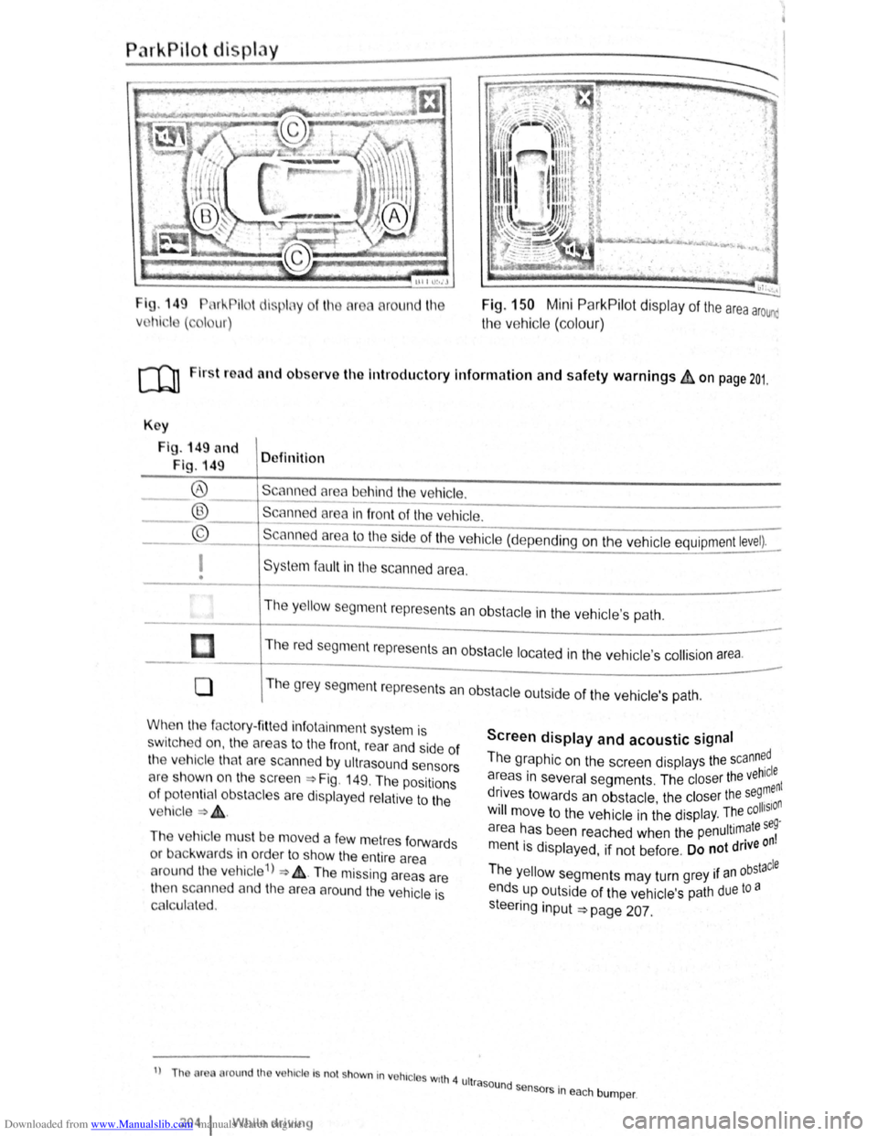
I g. 149 11 !--Pilot lispl y
Vl l~i ·I ( , I ur)
round l11e Fig. 150 Mini ParkPilot display of the area arounc
the vehic le (co lo ur)
ro Firs t road and ol>sorve the Introductory Information and safety warnings&, on page 201.
Key
Fig . 149 and
Fig. 149 Definition
Scann d
area behind the vehicle. ®
® ©
------------------------ -----------Scanned area in front of the ve hicle.
--------------------------------Scanned area to the ~ide of the vehic le (depe nding on the ve hicl e equipment level).
I
• Sys te m fa ult in the scanned area .
The
y ello w segm ent represents an obstacle in the vehic le's path .
Th e r
ed segment represents an obsta cle loca te d in the vehicle's collision a rea.
0 T he grey segment represents a n obstacle outside of the ve hicl e's path.
When the factory- fitt ed inf otainment syste m is
sw it c h ed on , the a reas to the front , rear and side of
the vehicle tha t are scanned by ultrasound sensors
cH e sh own o n the scree n =>Fig. 149. The positions
o f
potentia l obs tacles are displa ye d re lative to the
v e hic le
=> & .
The vehicle mus t be move d a fe w m etres forwards
or back war
ds in order to show the e ntire area
around the vehicle 1
) => & . The missing areas are
t11en scanned and the area around the vehic le is
Cf'llcula ted.
1
) Th or round th v hic le Is no t shown in vohrc l s wrth 4 ult
2o4 1 Whil e driving
Screen display and acoustic signal
The graphic on the screen displays the scann~dl
areas in several segments . The closer the veh~:nt
drives towards an obstacle the closer the se9, n . • olhSIO Will move to the ve hicle in the displ ay. The c .
a r
ea has been reache d when the penultimate se~
m entis displayed, if not be fore . Do not drive on
Th . bstacle e yello w segments may turn grey 1f an °
ends up outside of the vehi cle's path due to a
s teeri
ng input =>page 207.
rasound se .
n sors m eac h bumper .