Page 710 of 2453
WW-15
Front Wiper Arm
WIPER AND WASHER SYSTEMS
7. Front Wiper Arm
A: REMOVAL
CAUTION:
When standing up the wiper arm, be sure to
stand up the driver’s side wiper arm first, and
then passenger’s side wiper arm next. Also,
when putting the wiper arms back, be sure to
start with passenger’s side first, then driver’s
side next. Doing this in the reverse order may
cause the driver’s side wiper blade to hit the
passenger’s side wiper arm and cause damage.
1) Remove the cap.
2) Remove the nut and remove the wiper arm.
B: INSTALLATION
1) Install in the reverse order of removal.
2) Operate the wiper once.
3) Align the wiper blade to ceramic print point mark
(A) of front window panel.
Tightening torque:
Refer to “COMPONENT” of “General Descrip-
tion”.
NENT, General Description.>
C: ADJUSTMENT
Operate the wiper once. Align the wiper blade to
ceramic print point mark (A) of front window panel.
WW-00232
WW-00359
(A)
WW-00359
(A)
Page 711 of 2453

WW-16
Front Wiper Motor and Link
WIPER AND WASHER SYSTEMS
8. Front Wiper Motor and Link
A: REMOVAL
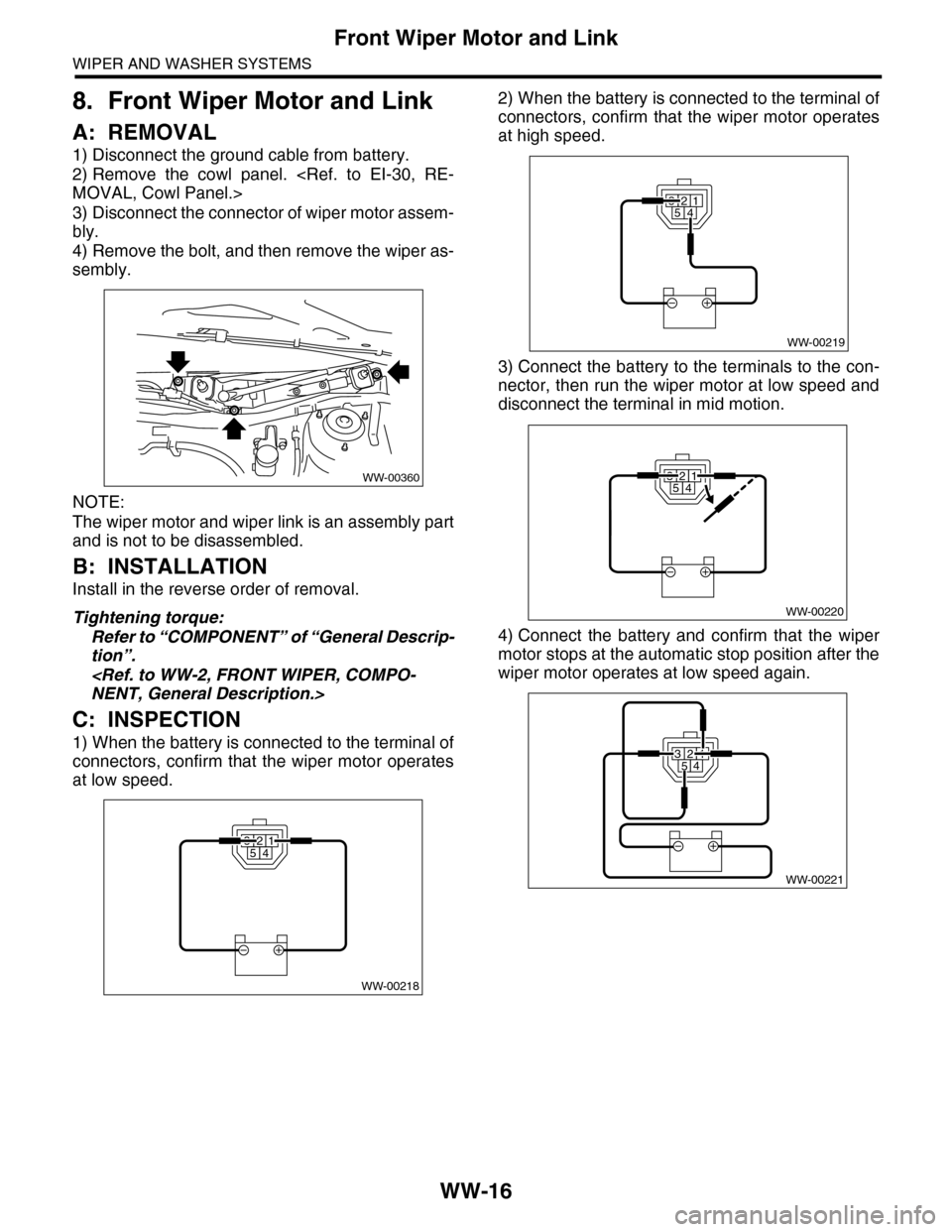
1) Disconnect the ground cable from battery.
2) Remove the cowl panel.
MOVAL, Cowl Panel.>
3) Disconnect the connector of wiper motor assem-
bly.
4) Remove the bolt, and then remove the wiper as-
sembly.
NOTE:
The wiper motor and wiper link is an assembly part
and is not to be disassembled.
B: INSTALLATION
Install in the reverse order of removal.
Tightening torque:
Refer to “COMPONENT” of “General Descrip-
tion”.
NENT, General Description.>
C: INSPECTION
1) When the battery is connected to the terminal of
connectors, confirm that the wiper motor operates
at low speed.
2) When the battery is connected to the terminal of
connectors, confirm that the wiper motor operates
at high speed.
3) Connect the battery to the terminals to the con-
nector, then run the wiper motor at low speed and
disconnect the terminal in mid motion.
4) Connect the battery and confirm that the wiper
motor stops at the automatic stop position after the
wiper motor operates at low speed again.
WW-00360
WW-00218
32541
32541
WW-00219
WW-00220
32541
WW-00221
32541
Page 712 of 2453

WW-17
Front Washer Nozzle
WIPER AND WASHER SYSTEMS
9. Front Washer Nozzle
A: REMOVAL
1) Remove the front hood insulator.
13, FRONT HOOD INSULATOR, REMOVAL,
Front Hood.>
2) Hold the claw (A) of the washer nozzle towards
the direction of the arrow, and remove the washer
nozzle.
3) Remove the washer hose from the washer noz-
zle.
B: INSTALLATION
1) Install in the reverse order of removal.
2) Adjust the washer nozzle position.
17, ADJUSTMENT, Front Washer Nozzle.>
C: INSPECTION
•Make sure the nozzle and hose are not clogged.
•Make sure the hose is not bent.
D: ADJUSTMENT
CAUTION:
Do not move the spray nozzle area directly to
adjust. Doing so will damage the slit and cause
improper spray.
1) Turn the wiper switch to OFF position.
2) While the vehicle is at a standstill, adjust the
washer injection position as shown in the figure.
Spray position:
A: 250 mm (9.84 in)
B: 433 mm (17.05 in)
3) Spray angle should be adjusted by rotating ad-
justing dial (A) with a flat tip screwdriver.
NOTE:
Adjusting dial will return to the original spray angle
with 1 rotation.
(1) Nozzle
(2) Spray center aiming position
(3) Spray area (shaded area)
Page 713 of 2453
WW-18
Rear Wiper Arm
WIPER AND WASHER SYSTEMS
10.Rear Wiper Arm
A: REMOVAL
1) Detach the wiper arm cover (A).
2) Remove the nut (B) to remove the wiper arm.
B: INSTALLATION
1) Install in the reverse order of removal.
2) Operate the rear wiper once.
3) Align the blade with the marking (A) of the glass.
Tightening torque:
Refer to “COMPONENT” of “General Descrip-
tion”.
General Description.>
C: ADJUSTMENT
1) Operate the rear wiper once.
2) Align the blade with the marking (A) of the glass.
WW-00179
(A)
(B)
WW-00361
(A)
WW-00361
(A)
Page 714 of 2453

WW-19
Rear Wiper Motor
WIPER AND WASHER SYSTEMS
11.Rear Wiper Motor
A: REMOVAL
1) Disconnect the ground cable from battery.
2) Remove the rear wiper arm.
REMOVAL, Rear Wiper Arm.>
3) Remove the rear gate lower trim.
REMOVAL, Rear Gate Trim.>
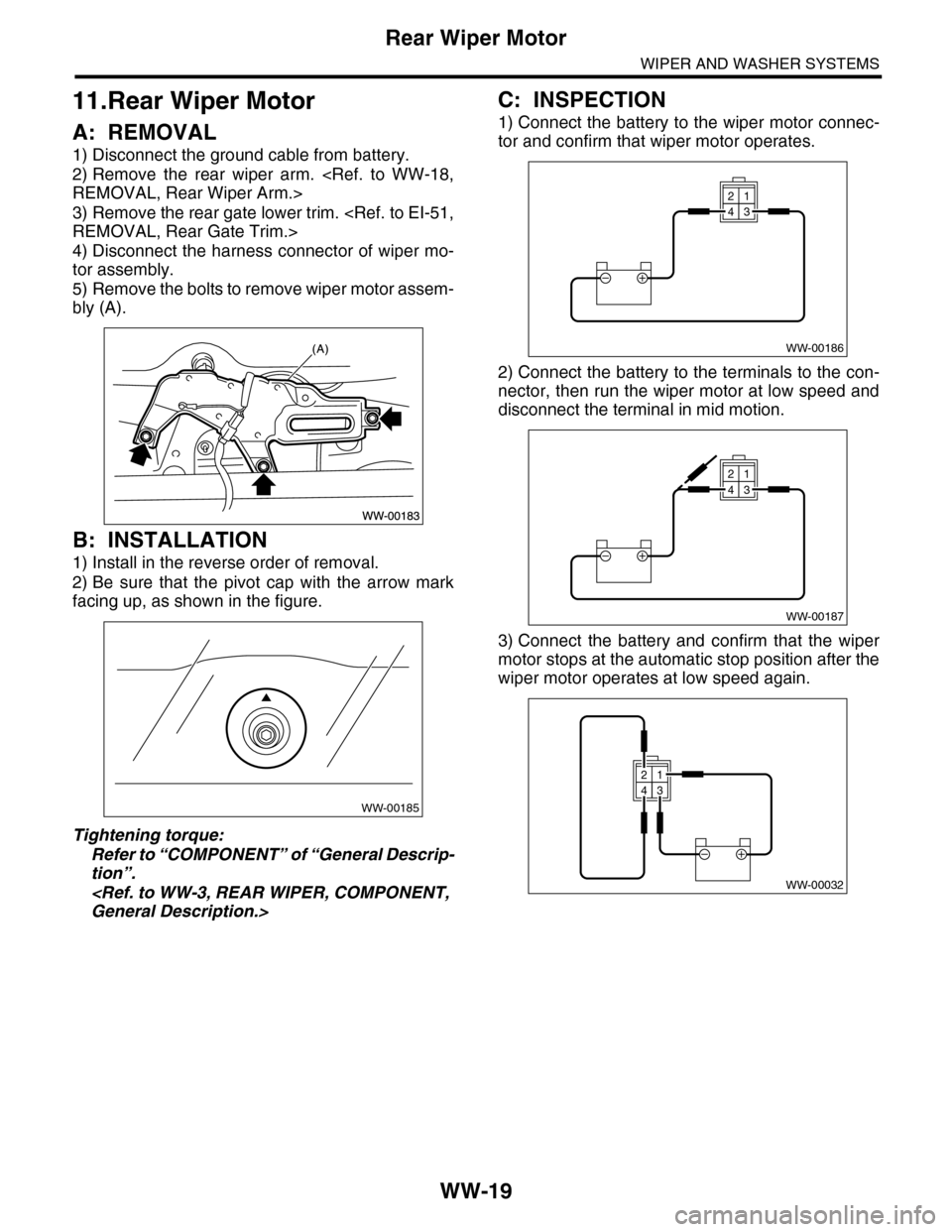
4) Disconnect the harness connector of wiper mo-
tor assembly.
5) Remove the bolts to remove wiper motor assem-
bly (A).
B: INSTALLATION
1) Install in the reverse order of removal.
2) Be sure that the pivot cap with the arrow mark
facing up, as shown in the figure.
Tightening torque:
Refer to “COMPONENT” of “General Descrip-
tion”.
General Description.>
C: INSPECTION
1) Connect the battery to the wiper motor connec-
tor and confirm that wiper motor operates.
2) Connect the battery to the terminals to the con-
nector, then run the wiper motor at low speed and
disconnect the terminal in mid motion.
3) Connect the battery and confirm that the wiper
motor stops at the automatic stop position after the
wiper motor operates at low speed again.
WW-00185
WW-00186
21
43
WW-00187
21
43
WW-00032
21
43
Page 715 of 2453
WW-20
Rear Washer
WIPER AND WASHER SYSTEMS
12.Rear Washer
A: REMOVAL
1) Detach the roof spoiler.
AL, Roof Spoiler.>
2) Remove the washer hose from washer nozzle.
3) Push the claw of the nozzle from the reverse
side of roof spoiler with a flat tip screwdriver or
equivalent, and remove the washer nozzle.
B: INSTALLATION
Install in the reverse order of removal.
C: INSPECTION
•Make sure the nozzle and hose are not clogged.
•Make sure the hose is not bent.
•While the vehicle is at a standstill, make sure that
the washer injection position is as shown in the fig-
ure.
NOTE:
Washer injection position can not be adjusted.
(1) Nozzle
(2) Upper edge of the rear gate glass
(A) 72 mm (2.83 in)
(B) 70°
WW-00214
Page 1164 of 2453
EN(H6DO)(diag)-3
Check List for Interview
ENGINE (DIAGNOSTICS)
2. Check List for Interview
A: CHECK
1. CHECK LIST No. 1
Check the following item when problem has occurred.
NOTE:
Use copies of this page for interviewing customers.
Customer’s name Engine No.
Date of sale Fuel brand
Date of repair Odometer readingkm
V. I . N . miles
Weather Fine
Cloudy
Rainy
Snowy
Various/Others:
Ambient air temperature °C (°F)
Hot
Warm
Cool
Cold
Place Highway
Suburbs
Inner city
Uphill
Downhill
Rough road
Others:
Engine temperature Cold
Warming-up
After warming-up
Any temperature
Others:
Engine speed rpm
Ve h i c l e s p e e d k m / h ( M P H )
Driving conditions Not affected
At starting
While idling
At racing
While accelerating
While cruising
While decelerating
While turning (RH/LH)
Headlight ON/ OFFRear defogger ON/ OFF
Blower ON/ OFFAudio ON/ OFF
A/C compressor ON/ OFFCar phone ON/ OFF
Radiator fan ON/ OFF
Fr o nt wi pe r ON/ OFF
Rear wiper ON/ OFF
Page 1189 of 2453

EN(H6DO)(diag)-28
Subaru Select Monitor
ENGINE (DIAGNOSTICS)
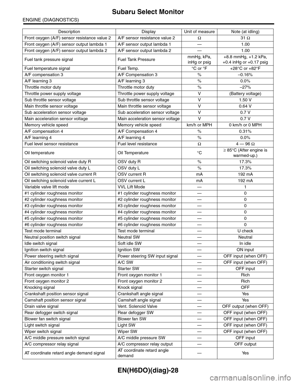
Fr o nt ox yg e n ( A / F) s en so r r es is t an ce val ue 2 A / F s en s or r e si st a nc e val u e 2Ω31 Ω
Fr o nt ox yg e n ( A / F) s en so r ou t p ut la m bd a 1 A / F s en s or o ut p ut l am bd a 1 — 1 . 00
Fr o nt ox yg e n ( A / F) s en so r ou t p ut la m bd a 2 A / F s en s or o ut p ut l am bd a 2 — 1 . 00
Fuel tank pressure signal Fuel Tank PressuremmHg, kPa,
inHg or psig
+8.8 mmHg, +1.2 kPa,
+0.4 inHg or +0.17 psig
Fuel temperature signal Fuel Temp. °C or °F +28°C or +82°F
A/F compensation 3 A/F Compensation 3 % –0.16%
A/F learning 3 A/F learning 3 % 0.0%
Throttle motor duty Throttle motor duty % –27%
Throttle power supply voltage Throttle power supply voltage V (Battery voltage)
Sub throttle sensor voltage Sub throttle sensor voltage V 1.50 V
Main throttle sensor voltage Main throttle sensor voltage V 0.64 V
Sub acceleration sensor voltage Sub acceleration sensor voltage V 0.7 V
Main acceleration sensor voltage Main acceleration sensor voltage V 0.7 V
Memory vehicle speed Memory vehicle speed km/h or MPH 0 km/h or 0 MPH
A/F compensation 4 A/F Compensation 4 % 0.31%
A/F learning 4 A/F learning 4 % 0.0%
Fuel level sensor resistance Fuel level resistanceΩ4 — 96 Ω
Oil temperature Oil Temperature °C≥ 85°C (After engine is
warmed-up.)
Oil switching solenoid valve duty R OSV duty R % 17.3%
Oil switching solenoid valve duty L OSV duty L % 17.3%
Oil switching solenoid valve current R OSV current R mA 192 mA
Oil switching solenoid valve current L OSV current L mA 192 mA
Va r i a b l e va l v e l i f t m o d e V V L L i f t M o d e — 1
#1 cylinder roughness monitor #1 cylinder roughness monitor — 0
#2 cylinder roughness monitor #2 cylinder roughness monitor — 0
#3 cylinder roughness monitor #3 cylinder roughness monitor — 0
#4 cylinder roughness monitor #4 cylinder roughness monitor — 0
#5 cylinder roughness monitor #5 cylinder roughness monitor — 0
#6 cylinder roughness monitor #6 cylinder roughness monitor — 0
Te s t m o d e t e r m i n a l Te s t m o d e t e r m i n a l — U c h e c k
Neutral position switch signal Neutral SW — Neutral
Idle switch signal Soft idle SW — In idle
Ignition switch signal Ignition SW — ON input
Pow er s te e r in g sw it c h s ig n al Powe r st ee r i ng S W i n pu t si gn a l — O FF i np u t ( w h e n OF F )
Air conditioning switch signal A/C SW — OFF input (when OFF)
Starter switch signal Starter SW — OFF input
Fr o nt ox yg e n mo n it o r 1 Fr o n t oxy ge n m on i to r 1 — Ri ch
Fr o nt ox yg e n mo n it o r 2 Fr o n t oxy ge n m on i to r 2 — Ri ch
Knocking signal Knock signal — OFF
Crankshaft position sensor signal Crankshaft angle signal — Yes
Camshaft position sensor signal Camshaft angle signal — Yes
Drain valve signal Vent. Solenoid Valve — OFF output (when OFF)
Rear defogger switch signal Rear defogger SW — OFF input (when OFF)
Blower fan switch signal Blower fan SW — OFF input (when OFF)
Light switch signal Light SW — OFF input (when OFF)
Wiper switch signal Wiper SW — OFF input (when OFF)
A/C middle pressure switch signal A/C middle pressure SW — OFF input
A/C compressor relay signal A/C compressor relay output — OFF output
AT c o o r d i n a t e r e t a r d a n g l e d e m a n d s i g n a lAT c o o r d i n a t e r e t a r d a n g l e
demand—Yes
Description Display Unit of measure Note (at idling)