2009 SUBARU TRIBECA cruise control
[x] Cancel search: cruise controlPage 472 of 2453

LAN(diag)-16
Subaru Select Monitor
LAN SYSTEM (DIAGNOSTICS)
Immobilizer lamp output ON/OFFBody integrated unit output
valueOn when immobilizer pilot light blinks
Keyless operation 1 Registration/Nor malBody integrated unit input
value
Not supported by North American specifica-
tions
Keyless operation 2 Clear/Nor malBody integrated unit input
value
Not supported by North American specifica-
tions
CC Main Lamp On/Off CAN data input value
Cruise control switch on
Reception from ECM and transmission to
combination meter
CC Set Lamp On/Off CAN data input value
On when cruise control vehicle speed is set
Reception from ECM and transmission to
combination meter
SPORT Lamp On/Off CAN data input value
SPORT mode switch ON
Reception from TCM and transmission to
combination meter
SPORT Blink Blink/Off CAN data input value
TCM error signal reception ON
Reception from TCM and transmission to
combination meter
AT F Te m p e r a t u r e L a m p O n / O f f C A N d a t a i n p u t v a l u e
AT F o i l t e m p e r a t u r e r i s e O N
Reception from TCM and transmission to
combination meter
AT F B l i n k B l i n k / O f f C A N d a t a i n p u t v a l u eNot supported by North American specifica-
tions
Tire diameter abnormal 1 On/Off CAN data input valueNot supported by North American specifica-
tions
Tire diameter abnormal 2 Blink/Off CAN data input value
ON when difference in rotation between
front and rear wheels is 4% or more
Reception from TCM and transmission to
combination meter
SPORT Shift (UP) UP/OFFBody integrated unit input
valueON when shift lever can be operated up
SPORT Shift (DOWN) DOWN/OFFBody integrated unit input
valueON when shift lever can be operated down
SPORT Shift (buzzer 1) ON/OFF CAN data input valueReception from TCM and transmission to
combination meter
SPORT Shift (buzzer 2) ON/OFF CAN data input valueNot supported by North American specifica-
tions
ABS/VDC Judging ABS/VDC CAN data input valueTr a n s m i s s i o n f r o m v e h i c l e d y n a m i c c o n t r o l
(VDC) to high speed control module
ADA Existence Judging Yes/No CAN data input valueNot supported by North American specifica-
tions
Small light SW ON/OFFBody integrated unit input
valueOn when small light is illuminated
Headlight ON/OFFBody integrated unit output
value
Not supported by North American specifica-
tions
Headlight HI ON/OFFBody integrated unit output
value
Not supported by North American specifica-
tions
Tu r n s i g n a l L H O N / O F FBody integrated unit output
value
Not supported by North American specifica-
tions
Tu r n s i g n a l R H O N / O F FBody integrated unit output
value
Not supported by North American specifica-
tions
R defogger SW ON/OFFBody integrated unit output
valueRear defogger switch ON
Australia Judging Flag Australia/OthersBody integrated unit output
valueNorth American specifications have others
Large diameter tires Large diameter/othersBody integrated unit output
valueReception from combination meter
Items to be displayed Unit of measure Description Note
Page 883 of 2453
PS-3
General Description
POWER ASSISTED SYSTEM (POWER STEERING)
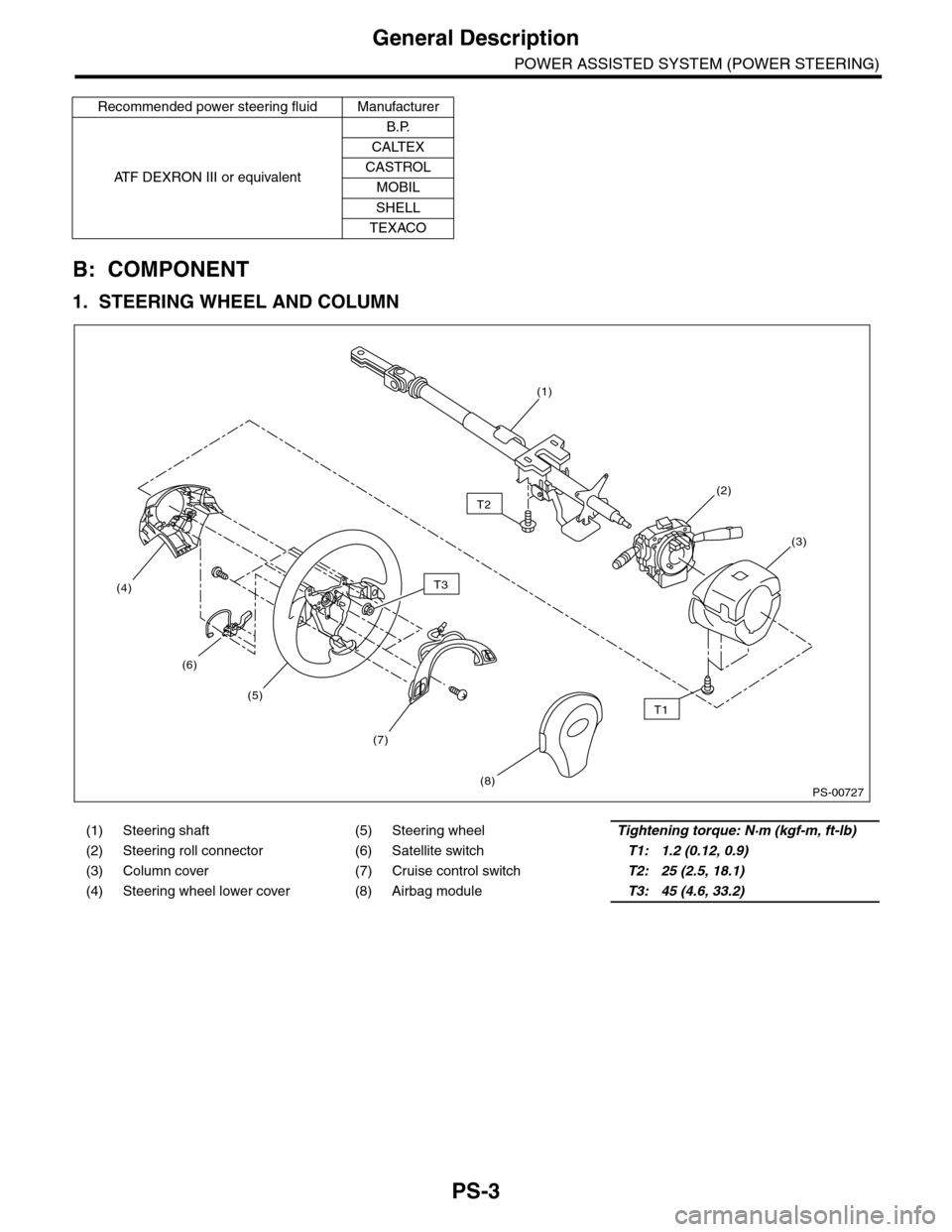
B: COMPONENT
1. STEERING WHEEL AND COLUMN
Recommended power steering fluid Manufacturer
AT F D E X R O N I I I o r e q u i v a l e n t
B.P.
CALTEX
CASTROL
MOBIL
SHELL
TEXACO
(1) Steering shaft (5) Steering wheelTightening torque: N·m (kgf-m, ft-lb)
(2) Steering roll connector (6) Satellite switchT1: 1.2 (0.12, 0.9)
(3) Column cover (7) Cruise control switchT2: 25 (2.5, 18.1)
(4) Steering wheel lower cover (8) Airbag moduleT3: 45 (4.6, 33.2)
PS-00727
T2
T1
T3
(5)
(1)
(2)
(3)
(4)
(8)
(6)
(7)
Page 1179 of 2453
EN(H6DO)(diag)-18
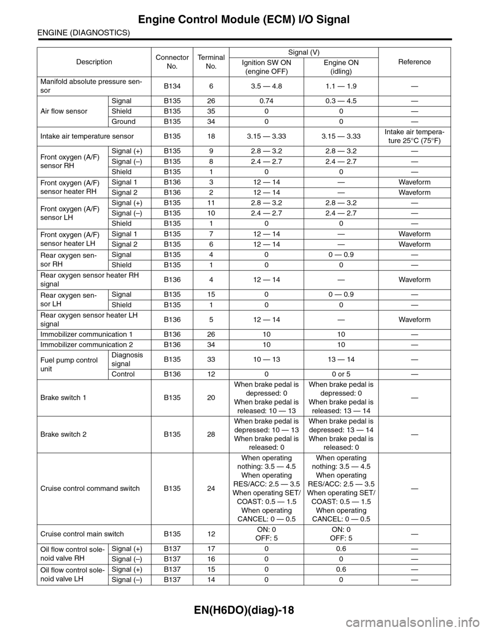
Engine Control Module (ECM) I/O Signal
ENGINE (DIAGNOSTICS)
Manifold absolute pressure sen-
sorB134 6 3.5 — 4.8 1.1 — 1.9 —
Air flow sensor
Signal B135 26 0.74 0.3 — 4.5 —
Shield B135 35 0 0 —
Ground B135 34 0 0 —
Intake air temperature sensor B135 18 3.15 — 3.33 3.15 — 3.33Intake air tempera-
ture 25°C (75°F)
Fr o nt ox yg e n ( A / F)
sensor RH
Signal (+) B135 9 2.8 — 3.2 2.8 — 3.2 —
Signal (–) B135 8 2.4 — 2.7 2.4 — 2.7 —
Shield B135 1 0 0 —
Fr o nt ox yg e n ( A / F)
sensor heater RH
Signal 1 B136 3 12 — 14 — Waveform
Signal 2 B136 2 12 — 14 — Waveform
Fr o nt ox yg e n ( A / F)
sensor LH
Signal (+) B135 11 2.8 — 3.2 2.8 — 3.2 —
Signal (–) B135 10 2.4 — 2.7 2.4 — 2.7 —
Shield B135 1 0 0 —
Fr o nt ox yg e n ( A / F)
sensor heater LH
Signal 1 B135 7 12 — 14 — Waveform
Signal 2 B135 6 12 — 14 — Waveform
Rear oxygen sen-
sor RH
Signal B135 4 0 0 — 0.9 —
Shield B135 1 0 0 —
Rear oxygen sensor heater RH
signalB136 4 12 — 14 — Waveform
Rear oxygen sen-
sor LH
Signal B135 15 0 0 — 0.9 —
Shield B135 1 0 0 —
Rear oxygen sensor heater LH
signalB136 5 12 — 14 — Waveform
Immobilizer communication 1 B136 26 10 10 —
Immobilizer communication 2 B136 34 10 10 —
Fuel pump control
unit
Diagnosis
signalB135 33 10 — 13 13 — 14 —
Control B136 12 0 0 or 5 —
Brake switch 1 B135 20
When brake pedal is
depressed: 0
When brake pedal is
released: 10 — 13
When brake pedal is
depressed: 0
When brake pedal is
released: 13 — 14
—
Brake switch 2 B135 28
When brake pedal is
depressed: 10 — 13
When brake pedal is
released: 0
When brake pedal is
depressed: 13 — 14
When brake pedal is
released: 0
—
Cruise control command switch B135 24
When operating
nothing: 3.5 — 4.5
When operating
RES/ACC: 2.5 — 3.5
When operating SET/
COAST: 0.5 — 1.5
When operating
CANCEL: 0 — 0.5
When operating
nothing: 3.5 — 4.5
When operating
RES/ACC: 2.5 — 3.5
When operating SET/
COAST: 0.5 — 1.5
When operating
CANCEL: 0 — 0.5
—
Cruise control main switch B135 12ON: 0
OFF: 5
ON: 0
OFF: 5—
Oil flow control sole-
noid valve RH
Signal (+) B137 17 0 0.6 —
Signal (–) B137 16 0 0 —
Oil flow control sole-
noid valve LH
Signal (+) B137 15 0 0.6 —
Signal (–) B137 14 0 0 —
DescriptionConnector
No.
Te r m i n a l
No.
Signal (V)
ReferenceIgnition SW ON
(engine OFF)
Engine ON
(idling)
Page 1190 of 2453
![SUBARU TRIBECA 2009 1.G Service Workshop Manual EN(H6DO)(diag)-29
Subaru Select Monitor
ENGINE (DIAGNOSTICS)
5. READ CURRENT DATA FOR ENGINE (OBD MODE)
1) On the «Main Menu» display screen, select the {Each System Check} and press the [YES] key.
SUBARU TRIBECA 2009 1.G Service Workshop Manual EN(H6DO)(diag)-29
Subaru Select Monitor
ENGINE (DIAGNOSTICS)
5. READ CURRENT DATA FOR ENGINE (OBD MODE)
1) On the «Main Menu» display screen, select the {Each System Check} and press the [YES] key.](/manual-img/17/7322/w960_7322-1189.png)
EN(H6DO)(diag)-29
Subaru Select Monitor
ENGINE (DIAGNOSTICS)
5. READ CURRENT DATA FOR ENGINE (OBD MODE)
1) On the «Main Menu» display screen, select the {Each System Check} and press the [YES] key.
2) On the «System Selection Menu» display screen, select the {Engine} and press the [YES] key.
3) Press the [YES] key after the information of engine type has been displayed.
4) On the «Engine Diagnosis» display screen, select the {OBD System} and press the [YES] key.
5) On the «OBD Menu» display screen, select the {Current Data Display/Save}, and then press the [YES]
key.
6) On the «Data Display Menu» screen, select the {Data Display} and press the [YES] key.
7) Using the scroll key, scroll the display screen up or down until the desired data is shown.
•A list of the support data is shown in the following table.
AT c o o r d i n a t e f u e l c u t d e m a n d s i g n a l AT c o o r d i n a t e f u e l c u t d e m a n d — O F F
Ve h i c l e d y n a m i c s c o n t r o l ( V D C ) t o r q u e d o w n
prohibition outputBan of Torque Down — Permission
Ve h i c l e d y n a m i c s c o n t r o l ( V D C ) t o r q u e d o w n
demandVDC torque down demand — OFF
AT c o o r d i n a t e p e r m i s s i o n s i g n a l AT c o o r d i n a t e p e r m i s s i o n s i g n a l — P e r m i s s i o n
Electronic throttle control motor relay signal ETC motor relay — ON
Stop light switch signal Stop Light Switch — OFF
SET/COAST switch signal SET/COAST SW — OFF
RESUME/ACCEL switch signal RESUME/ACCEL SW — OFF
Brake switch signal Brake SW — OFF
Main switch signal Main SW — OFF
Body integrated unit data reception Body Int. Unit Data — Yes
Body integlated unit counter update Body Int. Unit Count — Yes
Cruise control cancel switch signal CC Cancel SW — OFF
Va r i a b l e v a l v e l i f t d i a g n o s i s o i l p r e s s u r e sw i t c h
signal 1Oil Temperature SW1 — ON
Va r i a b l e v a l v e l i f t d i a g n o s i s o i l p r e s s u r e sw i t c h
signal 2Oil Temperature SW2 — ON
Description Display Unit of measure
Number of diagnosis code Number of Diag. Codes: 0
Condition of malfunction indicator light MI (MIL) ON or OFF
Monitoring test of misfire Misfire monitoring Finish
Monitoring test of fuel system Fuel system monitoring Finish
Monitoring test of comprehensive component Component monitoring Finish
Te s t o f c a t a l y s t C a t a l y s t D i a g n o s i s F i n i s h o r i n c o m p l e t e
Te s t o f h e a t i n g - t y p e c a t a l y s t H e a t e d c a t a l y s t N o
Te s t o f e v a p o r a t i v e e m i s s i o n p u r g e c o n t r o l s y s t e m E v a p o r a t i v e p u r g e s y s t e m F i n i s h o r i n c o m p l e t e
Te s t o f s e c o n d a r y a i r s y s t e m S e c o n d a r y a i r s y s t e m N o
Te s t o f a i r c o n d i t i o n i n g s y s t e m r e f r i g e r a n t A / C s y s t e m r e f r i g e r a n t N o
Te s t o f o x y g e n s e n s o r O x y g e n s e n o r F i n i s h o r i n c o m p l e t e
Te s t o f o x y g e n s e n s o r h e a t e r O x y g e n s e n s o r h e a t e r F i n i s h
Te s t o f E G R s y s t e m E G R s y s t e m N o s u p p o r t
A/F control #1 Fuel system for Bank 1 OPEN early period
A/F control #2 Fuel system for Bank 2 OPEN early period
Calculated load valve Calculated load valve %
Engine coolant temperature Coolant Temp. °C
A/F compensation #1 Short term fuel trim B1 %
A/F learning #1 Long term fuel trim B1 %
A/F compensation #2 Short term fuel trim #2 %
A/F learning #2 Long term fuel trim B2 %
Description Display Unit of measure Note (at idling)
Page 1193 of 2453
![SUBARU TRIBECA 2009 1.G Service Workshop Manual EN(H6DO)(diag)-32
Subaru Select Monitor
ENGINE (DIAGNOSTICS)
7. LED OPERATION MODE FOR ENGINE
1) On the «Main Menu» display screen, select the {Each System Check} and press the [YES] key.
2) On the SUBARU TRIBECA 2009 1.G Service Workshop Manual EN(H6DO)(diag)-32
Subaru Select Monitor
ENGINE (DIAGNOSTICS)
7. LED OPERATION MODE FOR ENGINE
1) On the «Main Menu» display screen, select the {Each System Check} and press the [YES] key.
2) On the](/manual-img/17/7322/w960_7322-1192.png)
EN(H6DO)(diag)-32
Subaru Select Monitor
ENGINE (DIAGNOSTICS)
7. LED OPERATION MODE FOR ENGINE
1) On the «Main Menu» display screen, select the {Each System Check} and press the [YES] key.
2) On the «System Selection Menu» display screen, select the {Engine} and press the [YES] key.
3) Press the [YES] key after the information of engine type has been displayed.
4) On the «Engine Diagnosis» display screen, select the {Current Data Display/Save}, and then press the
[YES] key.
5) On the «Data Display» screen, select the {Data LED Display} and press the [YES] key.
6) Using the scroll key, scroll the display screen up or down until the desired data is shown.
•A list of the support data is shown in the following table.
NOTE:
For detailed operation procedure, refer to the “SUBARU SELECT MONITOR OPERATION MANUAL”.
Description Display Message When LED “ON” required
Te s t m o d e s i g n a l Te s t m o d e t e r m i n a l D c h e c k / U c h e c k D c h e c k
Neutral position switch signal Neutral SW Neutral/Other than neutral Neutral
Idle switch signal Soft idle SW Idle/Other than idle In idle
Ignition switch signal Ignition SW ON Input/OFF Input ON input
Pow er s te e r in g sw it c h s ig n al Pow er s te e r in g S W ON I np u t/ O FF I np u t ON i np ut
Air conditioning switch signal A/C SW ON Input/OFF Input ON input
Starter switch signal Starter SW ON Input/OFF Input ON input
Fr o nt ox yg e n mo n it o r 1 Ft O 2 mo n it o r 1 Le a n/ Ri ch Ric h
Fr o nt ox yg e n mo n it o r 2 Ft O 2 mo n it o r 2 Le a n/ Ri ch Ric h
Knocking signal Knock signal Yes/No Yes
Crankshaft position sensor signal Crankshaft angle signal Yes/No Yes
Camshaft position sensor signal Camshaft angle signal Yes/No Yes
Rear defogger switch signal Rear defogger SW ON Input/OFF Input ON input
Blower fan switch signal Blower fan SW ON Input/OFF Input ON input
Light switch signal Light SW ON Input/OFF Input ON input
Wiper switch signal Wiper SW ON Input/OFF Input ON input
A/C middle pressure switch signal A/C middle pressure SW ON Input/OFF Input ON input
Air conditioner compressor relay sig-
nalCompressor relay ON output/OFF output ON output
Drain valve signal Vent. Solenoid Valve ON or OFF When drain valve is ON.
AT r e t a r d a n g l e d e m a n d s i g n a l AT r e t a r d a n g l e d e m a n d Ye s / N o Ye s
AT f u e l c u t s i g n a l AT f u e l c u t Ye s / N o Ye s
VDC torque down prohibition output Torque down output ON/OFF Prohibition
VDC torque down demand Torque down demand Yes/No Yes
AT c o o r d i n a t e p e r m i s s i o n s i g n a lAT c o o r d i n a t e p e r m i s s i o n
signalON/OFF Permission
Electronic throttle control motor relay
signalETC motor relay ON/OFF ON
Stop light switch signal Stop SW ON Input/OFF Input ON input
SET/COAST switch signal SET/CST SW ON Input/OFF Input ON input
RESUME/ACCEL switch signal RES/ACC SW ON Input/OFF Input ON input
Brake switch signal Brake SW ON Input/OFF Input ON input
Main switch signal Main SW ON Input/OFF Input ON input
Body integrated unit data reception Body Int. Unit Data Yes/No Yes
Body integrated unit counter update Body Int. Unit Count Yes/No Yes
Cruise control cancel switch signal CC Cancel SW ON Input/OFF Input ON input
Va r i a b l e va l v e l i f t d i a g n o s i s o i l p r e s -
sure switch signal 1Oil Temperature SW1 ON/OFF ON
Va r i a b l e va l v e l i f t d i a g n o s i s o i l p r e s -
sure switch signal 2Oil Temperature SW2 ON/OFF ON
Page 1785 of 2453
GD(H6DO)-173
Diagnostic Trouble Code (DTC) Detecting Criteria
GENERAL DESCRIPTION
DA:DTC P0607 CONTROL MODULE PERFORMANCE
1. OUTLINE OF DIAGNOSIS
Judge as NG when either the following is completed.
•When the read value of throttle position sensor 1 signal is mismatched between main CPU and sub CPU.
•When the read value of accelerator position sensor 1 signal is mismatched between main CPU and sub
CPU.
•When the sub CPU operates abnormally.
•When the communication between main CPU ←→ sub CPU is abnormal.
•When the input amplifier circuit of throttle position sensor 1 is abnormal.
•When the cruise control cannot be canceled correctly.
•When the signal of brake SW1 and 2 is mismatched.
•When the directed angle from the main CPU is abnormal.
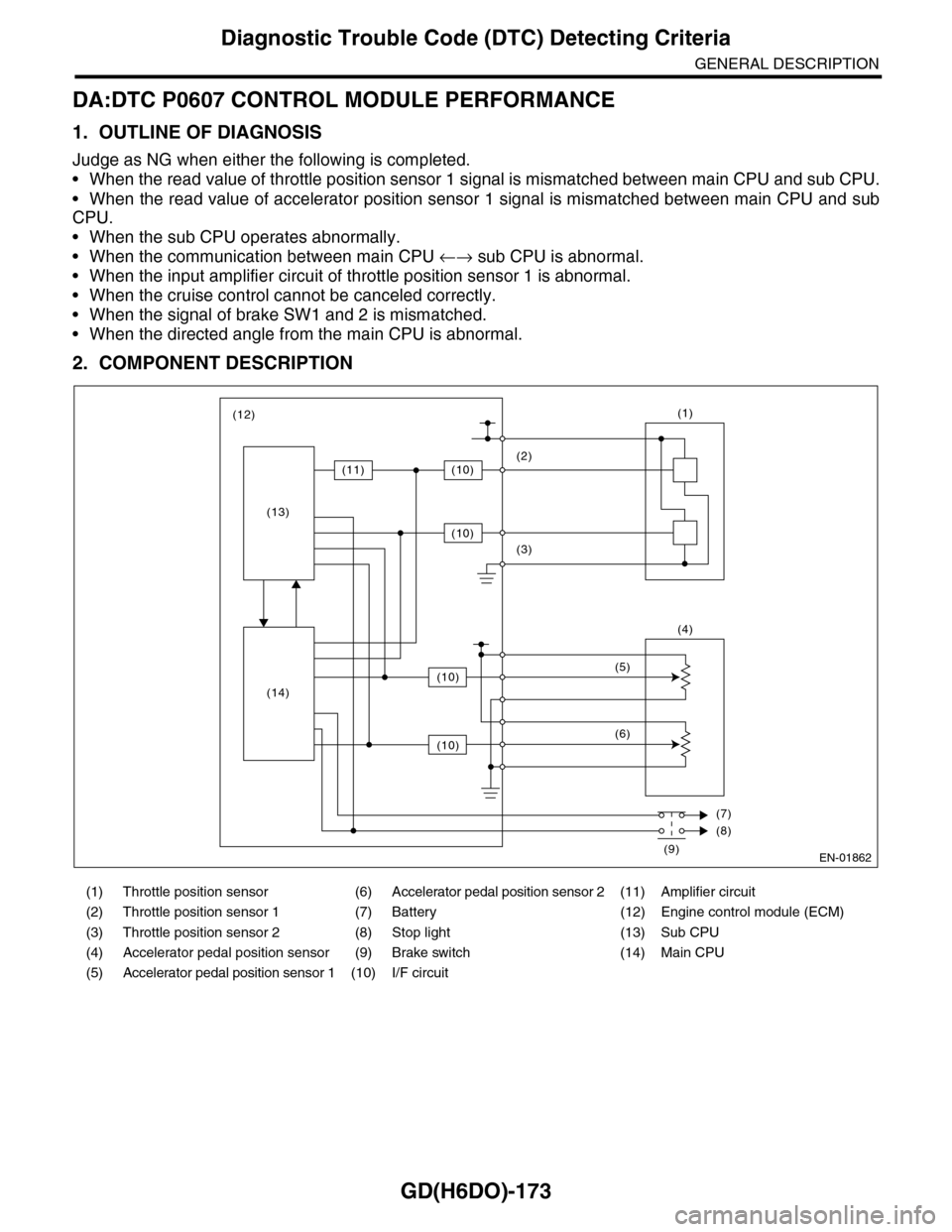
2. COMPONENT DESCRIPTION
(1) Throttle position sensor (6) Accelerator pedal position sensor 2 (11) Amplifier circuit
(2) Throttle position sensor 1 (7) Battery (12) Engine control module (ECM)
(3) Throttle position sensor 2 (8) Stop light (13) Sub CPU
(4) Accelerator pedal position sensor (9) Brake switch (14) Main CPU
(5) Accelerator pedal position sensor 1 (10) I/F circuit
EN-01862
(1)
(4)
(2)
(3)
(5)
(6)
(7)
(8)
(9)
(12)
(11)(10)
(10)
(10)
(10)
(13)
(14)
Page 1786 of 2453
GD(H6DO)-174
Diagnostic Trouble Code (DTC) Detecting Criteria
GENERAL DESCRIPTION
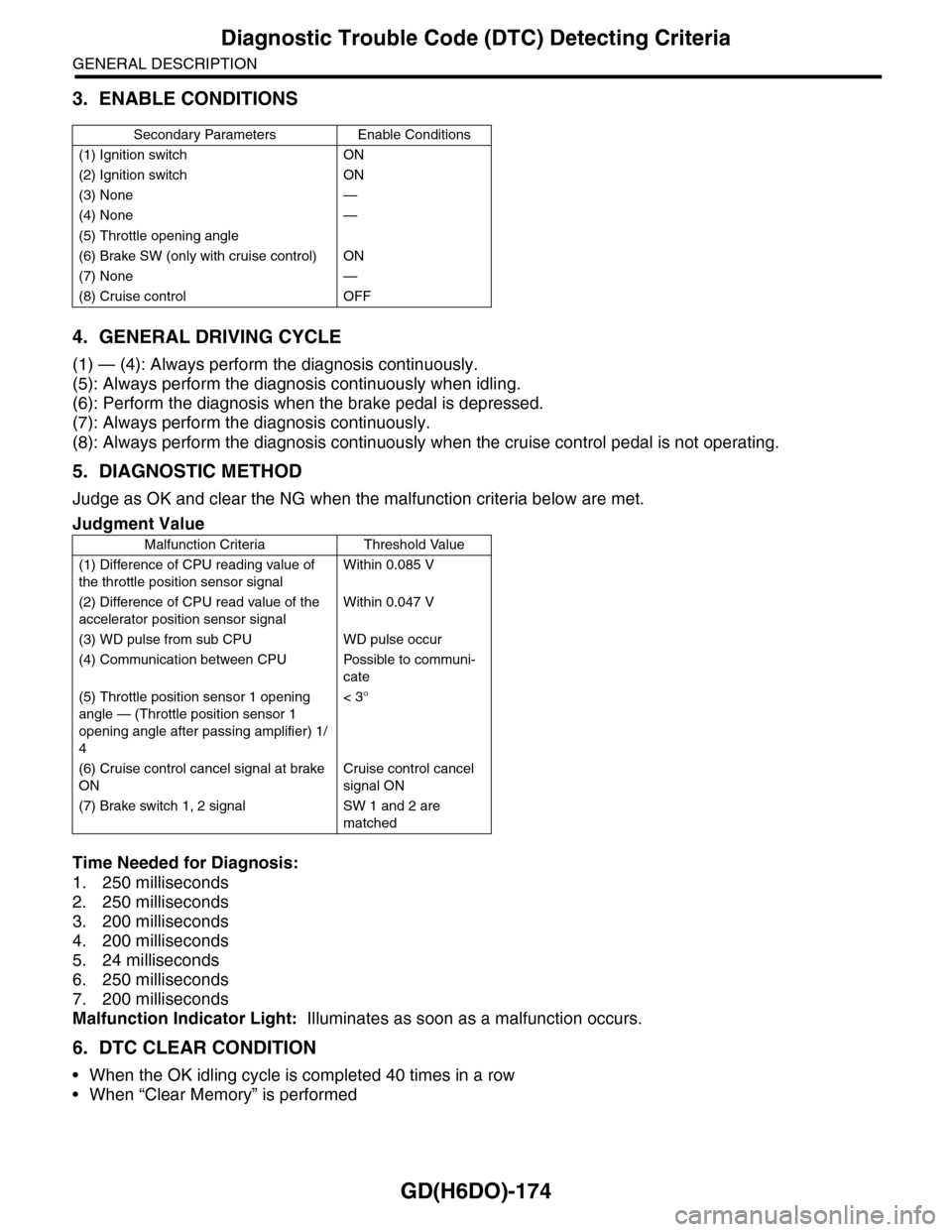
3. ENABLE CONDITIONS
4. GENERAL DRIVING CYCLE
(1) — (4): Always perform the diagnosis continuously.
(5): Always perform the diagnosis continuously when idling.
(6): Perform the diagnosis when the brake pedal is depressed.
(7): Always perform the diagnosis continuously.
(8): Always perform the diagnosis continuously when the cruise control pedal is not operating.
5. DIAGNOSTIC METHOD
Judge as OK and clear the NG when the malfunction criteria below are met.
Time Needed for Diagnosis:
1. 250 milliseconds
2. 250 milliseconds
3. 200 milliseconds
4. 200 milliseconds
5. 24 milliseconds
6. 250 milliseconds
7. 200 milliseconds
Malfunction Indicator Light: Illuminates as soon as a malfunction occurs.
6. DTC CLEAR CONDITION
•When the OK idling cycle is completed 40 times in a row
•When “Clear Memory” is performed
Secondary Parameters Enable Conditions
(1) Ignition switch ON
(2) Ignition switch ON
(3) None —
(4) None —
(5) Throttle opening angle
(6) Brake SW (only with cruise control) ON
(7) None —
(8) Cruise control OFF
Judgment Value
Malfunction Criteria Threshold Value
(1) Difference of CPU reading value of
the throttle position sensor signal
Within 0.085 V
(2) Difference of CPU read value of the
accelerator position sensor signal
Within 0.047 V
(3) WD pulse from sub CPU WD pulse occur
(4) Communication between CPU Possible to communi-
cate
(5) Throttle position sensor 1 opening
angle — (Throttle position sensor 1
opening angle after passing amplifier) 1/
4
< 3°
(6) Cruise control cancel signal at brake
ON
Cruise control cancel
signal ON
(7) Brake switch 1, 2 signal SW 1 and 2 are
matched
Page 2133 of 2453
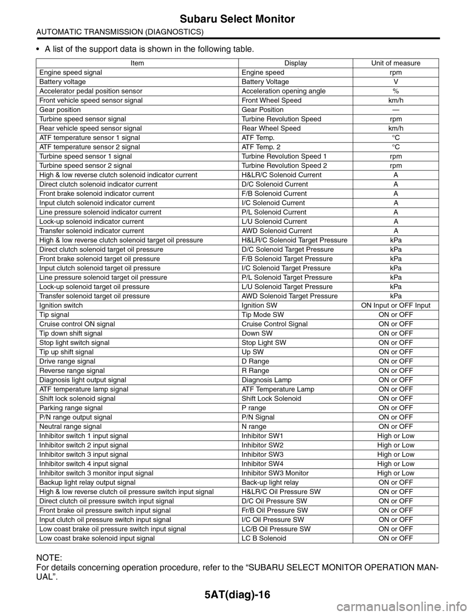
5AT(diag)-16
Subaru Select Monitor
AUTOMATIC TRANSMISSION (DIAGNOSTICS)
•A list of the support data is shown in the following table.
NOTE:
For details concerning operation procedure, refer to the “SUBARU SELECT MONITOR OPERATION MAN-
UAL”.
Item Display Unit of measure
Engine speed signal Engine speed rpm
Battery voltage Battery Voltage V
Accelerator pedal position sensor Acceleration opening angle %
Fr o nt veh ic l e sp e ed se n so r s ig n al Fr o n t W h ee l S p e ed km/ h
Gear position Gear Position —
Tu r b i n e s p e e d s e n s o r s i g n a l Tu r b i n e R e v o l u t i o n S p e e d r p m
Rear vehicle speed sensor signal Rear Wheel Speed km/h
ATF temperature sensor 1 signal ATF Temp. °C
ATF temperature sensor 2 signal ATF Temp. 2 °C
Tu r b i n e s p e e d s e n s o r 1 s i g n a l Tu r b i n e R e v o l u t i o n S p e e d 1 r p m
Tu r b i n e s p e e d s e n s o r 2 s i g n a l Tu r b i n e R e v o l u t i o n S p e e d 2 r p m
High & low reverse clutch solenoid indicator current H&LR/C Solenoid Current A
Direct clutch solenoid indicator current D/C Solenoid Current A
Fr o nt b rake so l en oi d in di c at o r c u rr e n t F / B S o l en o id Cur r e nt A
Input clutch solenoid indicator current I/C Solenoid Current A
Line pressure solenoid indicator current P/L Solenoid Current A
Lock-up solenoid indicator current L/U Solenoid Current A
Tr a n s f e r s o l e n o i d i n d i c a t o r c u r r e n t A W D S o l e n o i d C u r r e n t A
High & low reverse clutch solenoid target oil pressure H&LR/C Solenoid Target Pressure kPa
Direct clutch solenoid target oil pressure D/C Solenoid Target Pressure kPa
Fr o nt b rake so l en oi d ta r g et o il pr e ss ur e F / B S o l en o id Ta r g et P r es su r e kPa
Input clutch solenoid target oil pressure I/C Solenoid Target Pressure kPa
Line pressure solenoid target oil pressure P/L Solenoid Target Pressure kPa
Lock-up solenoid target oil pressure L/U Solenoid Target Pressure kPa
Tr a n s f e r s o l e n o i d t a r g e t o i l p r e s s u r e A W D S o l e n o i d Ta r g e t P r e s s u r e k P a
Ignition switch Ignition SW ON Input or OFF Input
Tip signal Tip Mode SW ON or OFF
Cruise control ON signal Cruise Control Signal ON or OFF
Tip down shift signal Down SW ON or OFF
Stop light switch signal Stop Light SW ON or OFF
Tip up shift signal Up SW ON or OFF
Drive range signal D Range ON or OFF
Reverse range signal R Range ON or OFF
Diagnosis light output signal Diagnosis Lamp ON or OFF
AT F t e m p e r a t u r e l a m p s i g n a l AT F Te m p e r a t u r e L a m p O N o r O F F
Shift lock solenoid signal Shift Lock Solenoid ON or OFF
Par king range signal P range ON or OFF
P/N range output signal P/N Signal ON or OFF
Neutral range signal N range ON or OFF
Inhibitor switch 1 input signal Inhibitor SW1 High or Low
Inhibitor switch 2 input signal Inhibitor SW2 High or Low
Inhibitor switch 3 input signal Inhibitor SW3 High or Low
Inhibitor switch 4 input signal Inhibitor SW4 High or Low
Inhibitor switch 3 monitor input signal Inhibitor SW3 Monitor High or Low
Backup light relay output signal Back-up light relay ON or OFF
High & low reverse clutch oil pressure switch input signal H&LR/C Oil Pressure SW ON or OFF
Direct clutch oil pressure switch input signal D/C Oil Pressure SW ON or OFF
Fr o nt b rake oi l pr e ss ur e swi tc h i n pu t si gn a l Fr / B Oi l P r e ss ur e S W ON or OF F
Input clutch oil pressure switch input signal I/C Oil Pressure SW ON or OFF
Low coast brake oil pressure switch input signal LC/B Oil Pressure SW ON or OFF
Low coast brake solenoid input signal LC B Solenoid ON or OFF