2009 SUBARU TRIBECA navi
[x] Cancel search: naviPage 521 of 2453

LAN(diag)-65
Diagnostic Procedure with Diagnostic Trouble Code (DTC)
LAN SYSTEM (DIAGNOSTICS)
R: DTC B0301 CAN-LS COUNTER ABNORMAL
DTC DETECTING CONDITION:
Find the unit in which trouble occurs and open or short CAN line, and repair and replace them.
(Free running counter error may be detected at the same time from the unit in which malfunction occurs.)
TROUBLE SYMPTOM:
“Er LC” is displayed in odo/trip meter.
WIRING DIAGRAM:
i128
1*
2*1*
2*
CAN JOINTCONNECTOR
i10
B283
A29A30
A27
A26
B26
B25
A: i84
B: B280B1
B14
TWISTED PAIR LINE
5467821931022 231112131415242526 2716171828 29192021 30
B280
i84
1234567891011121314151617181920212223242526272829303132333435
2345 678912 13 14 15 16 17 18 19 20 21 2210111
B283
i10
COMBINATIONMETER
BODYINTEGRATEDUNIT
AUTO A/CCONTROLMODULE
123456789101112
LAN00193
A:
B:
2*
1*
A6
A14
FRONTMONITOR
21
22MFD
2* :TERMINAL NO. OPTIONAL ARRANGEMENT AMONG 7, 8, 9, 10, 11 AND 12
1* :TERMINAL NO. OPTIONAL ARRANGEMENT AMONG 1, 2, 3, 4, 5 AND 6
i119
i122
A:
A:
A:
i119A:
i122
i128B:
MFDNAVI
MFD
NAVI
9
19 20
105672143131211
14 15 16 17
8
18222125262423
12345678910 11 12 13 14 15 16
345 678919 20 2114 15 16 17 1812101211 13 22
Step Check Yes No
1CHECK AUTO A/C CONTROL MODULE.
1) Display the current data of body integrated
unit using Subaru Select Monitor.
2) Display the number of blower fan levels in
the analog data.
3) Read the data display when the number of
blower fan levels is changed on air conditioner
control part.
Does the data display change? Go to step 2.Go to step 3.
Page 523 of 2453

LAN(diag)-67
Diagnostic Procedure with Diagnostic Trouble Code (DTC)
LAN SYSTEM (DIAGNOSTICS)
S: DTC B0302 CAN-LS BUS OFF
DTC DETECTING CONDITION:
Because of a lot of error data occurred, some units have been disconnected not to affect other units.
Communication error from the unit in which error is occurred is input at the same time.
TROUBLE SYMPTOM:
“Er LC” is displayed in odo/trip meter.
WIRING DIAGRAM:
i128
1*
2*1*
2*
CAN JOINTCONNECTOR
i10
B283
A29A30
A27
A26
B26
B25
A: i84
B: B280B1
B14
TWISTED PAIR LINE
5467821931022 231112131415242526 2716171828 29192021 30
B280
i84
1234567891011121314151617181920212223242526272829303132333435
2345 678912 13 14 15 16 17 18 19 20 21 2210111
B283
i10
COMBINATIONMETER
BODYINTEGRATEDUNIT
AUTO A/CCONTROLMODULE
123456789101112
LAN00193
A:
B:
2*
1*
A6
A14
FRONTMONITOR
21
22MFD
2* :TERMINAL NO. OPTIONAL ARRANGEMENT AMONG 7, 8, 9, 10, 11 AND 12
1* :TERMINAL NO. OPTIONAL ARRANGEMENT AMONG 1, 2, 3, 4, 5 AND 6
i119
i122
A:
A:
A:
i119A:
i122
i128B:
MFDNAVI
MFD
NAVI
9
19 20
105672143131211
14 15 16 17
8
18222125262423
12345678910 11 12 13 14 15 16
345 678919 20 2114 15 16 17 1812101211 13 22
Step Check Yes No
1CHECK AUTO A/C CONTROL MODULE.
1) Display the current data of body integrated
unit using Subaru Select Monitor.
2) Display the number of blower fan levels in
the analog data.
3) Read the data display when the number of
blower fan levels is changed on air conditioner
control part.
Does the data display change? Go to step 2.Go to step 3.
Page 525 of 2453

LAN(diag)-69
Diagnostic Procedure with Diagnostic Trouble Code (DTC)
LAN SYSTEM (DIAGNOSTICS)
T: DTC B0311 CAN-LS METER UNIT DATA ABNORMAL
DTC DETECTING CONDITION:
Combination meter has error, the harness between main harness splice and combination meter is open or
shorted, the connector is not connected properly, or the terminal has poor caulking.
TROUBLE SYMPTOM:
“Er Lc” is displayed in odo/trip meter.
WIRING DIAGRAM:
i128
1*
2*1*
2*
CAN JOINTCONNECTOR
i10
B283
A29A30
A27
A26
B26
B25
A: i84
B: B280B1
B14
TWISTED PAIR LINE
5467821931022 231112131415242526 2716171828 29192021 30
B280
i84
1234567891011121314151617181920212223242526272829303132333435
2345 678912 13 14 15 16 17 18 19 20 21 2210111
B283
i10
COMBINATIONMETER
BODYINTEGRATEDUNIT
AUTO A/CCONTROLMODULE
123456789101112
LAN00193
A:
B:
2*
1*
A6
A14
FRONTMONITOR
21
22MFD
2* :TERMINAL NO. OPTIONAL ARRANGEMENT AMONG 7, 8, 9, 10, 11 AND 12
1* :TERMINAL NO. OPTIONAL ARRANGEMENT AMONG 1, 2, 3, 4, 5 AND 6
i119
i122
A:
A:
A:
i119A:
i122
i128B:
MFDNAVI
MFD
NAVI
9
19 20
105672143131211
14 15 16 17
8
18222125262423
12345678910 11 12 13 14 15 16
345 678919 20 2114 15 16 17 1812101211 13 22
Step Check Yes No
1CHECK COMBINATION METER.
Perfor m the self-diagnosis of combination
meter.
Is the self-diagnosis OK? Read the DTC
again, and then
perform the diag-
nosis according to
DTC displayed on
the top.
Replace the com-
bination meter.
bination Meter.>
Page 526 of 2453

LAN(diag)-70
Diagnostic Procedure with Diagnostic Trouble Code (DTC)
LAN SYSTEM (DIAGNOSTICS)
U: DTC B0313 CAN-LS MONITOR DATA ABNORMAL
DTC DETECTING CONDITION:
Center display unit error, or harness between the main harness splice and center display unit is open or
shorted, the connector is not connected securely and the terminal has poor caulking.
TROUBLE SYMPTOM:
“Er LC” is displayed in odo/trip meter.
WIRING DIAGRAM:
i128
1*
2*1*
2*
CAN JOINTCONNECTOR
i10
B283
A29A30
A27
A26
B26
B25
A: i84
B: B280B1
B14
TWISTED PAIR LINE
5467821931022 231112131415242526 2716171828 29192021 30
B280
i84
1234567891011121314151617181920212223242526272829303132333435
2345 678912 13 14 15 16 17 18 19 20 21 2210111
B283
i10
COMBINATIONMETER
BODYINTEGRATEDUNIT
AUTO A/CCONTROLMODULE
123456789101112
LAN00193
A:
B:
2*
1*
A6
A14
FRONTMONITOR
21
22MFD
2* :TERMINAL NO. OPTIONAL ARRANGEMENT AMONG 7, 8, 9, 10, 11 AND 12
1* :TERMINAL NO. OPTIONAL ARRANGEMENT AMONG 1, 2, 3, 4, 5 AND 6
i119
i122
A:
A:
A:
i119A:
i122
i128B:
MFDNAVI
MFD
NAVI
9
19 20
105672143131211
14 15 16 17
8
18222125262423
12345678910 11 12 13 14 15 16
345 678919 20 2114 15 16 17 1812101211 13 22
Page 527 of 2453

LAN(diag)-71
Diagnostic Procedure with Diagnostic Trouble Code (DTC)
LAN SYSTEM (DIAGNOSTICS)
Step Check Yes No
1CHECK SUBARU SELECT MONITOR.
1) Display the current data of body integrated
unit using Subaru Select Monitor.
2) Display center monitor display fail.
Is OK displayed? Go to step 2.Refer to MFD or
navigation display.
gation Display.>
Function Display
(MFD).>
2CHECK NAVIGATION.
1) Display the current data of body integrated
unit using Subaru Select Monitor.
2) Display NAVI fail.
Is OK displayed? Refer to MFD or
navigation display.
gation Display.>
Function Display
(MFD).>
Refer to navigation
body.
Navigation Body.>
Page 530 of 2453

LAN(diag)-74
Diagnostic Procedure with Diagnostic Trouble Code (DTC)
LAN SYSTEM (DIAGNOSTICS)
W: DTC B0500 KEYLESS UART COM. MALFUNCTION
DTC DETECTING CONDITION:
UART between keyless control unit and body integrated unit is open or shorted, the connector is not con-
nected properly, or the terminal has poor caulking.
TROUBLE SYMPTOM:
Door lock does not operate with keyless.
WIRING DIAGRAM:
i128
1*
2*1*
2*
CAN JOINTCONNECTOR
i10
B283
A29A30
A27
A26
B26
B25
A: i84
B: B280B1
B14
TWISTED PAIR LINE
5467821931022 231112131415242526 2716171828 29192021 30
B280
i84
1234567891011121314151617181920212223242526272829303132333435
2345 678912 13 14 15 16 17 18 19 20 21 2210111
B283
i10
COMBINATIONMETER
BODYINTEGRATEDUNIT
AUTO A/CCONTROLMODULE
123456789101112
LAN00193
A:
B:
2*
1*
A6
A14
FRONTMONITOR
21
22MFD
2* :TERMINAL NO. OPTIONAL ARRANGEMENT AMONG 7, 8, 9, 10, 11 AND 12
1* :TERMINAL NO. OPTIONAL ARRANGEMENT AMONG 1, 2, 3, 4, 5 AND 6
i119
i122
A:
A:
A:
i119A:
i122
i128B:
MFDNAVI
MFD
NAVI
9
19 20
105672143131211
14 15 16 17
8
18222125262423
12345678910 11 12 13 14 15 16
345 678919 20 2114 15 16 17 1812101211 13 22
Step Check Yes No
1CHECK HARNESS.
1) Disconnect the body integrated unit con-
nector (i84) and keyless entry control unit con-
nector (i96).
2) Measure the resistance between har-
nesses.
Connector & terminal
(i84) No. 9 — (i96) No. 3:
Is the resistance less than 10
Ω?
Go to step 2.Repair the open
circuit of harness
or replace har-
ness.
Page 2304 of 2453

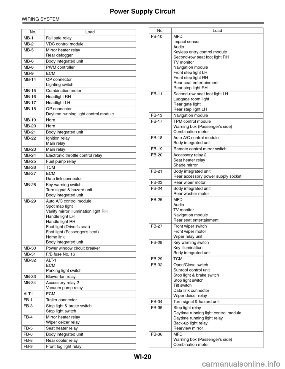
WI-20
Power Supply Circuit
WIRING SYSTEM
No. Load
MB-1 Fail safe relay
MB-2 VDC control module
MB-5 Mirror heater relay
Rear defogger
MB-6 Body integrated unit
MB-8 PWM controller
MB-9 ECM
MB-14 OP connector
Lighting switch
MB-15 Combination meter
MB-16 Headlight RH
MB-17 Headlight LH
MB-18 OP connector
Daytime running light control module
MB-19 Horn
MB-20 Horn
MB-21 Body integrated unit
MB-22 Ignition relay
Main relay
MB-23 Main relay
MB-24 Electronic throttle control relay
MB-25 Fuel pump relay
MB-26 TCM
MB-27 ECM
Data link connector
MB-28 Key warning switch
Tu r n s i g n a l & h a z a r d u n i t
Body integrated unit
MB-29 Auto A/C control module
Spot map light
Va n i t y m i r r o r i l l u m i n a t i o n l i g h t R H
Handle light LH
Handle light RH
Foot light (Driver’s seat)
Foot light (Passenger’s seat)
Home link
Body integrated unit
MB-30 Power window circuit breaker
MB-31 F/B fuse No. 16
MB-32 ALT-1
ECM
Par king light switch
MB-33 Blower fan relay
MB-34 Accessory relay 2
Va c u u m p u m p r e l ay
ALT-1 ECM
FB-1 Trailer connector
FB-3 Stop light & brake switch
Stop light switch
FB-4 Mirror heater relay
Wiper deicer relay
FB-5 Seat heater relay
FB-6 Body integrated unit
FB-8 Rear cooler relay
FB-9 Front fog light relay
FB-10 MFD
Impact sensor
Audio
Keyless entr y control module
Second-row seat foot light RH
TV monitor
Navigation module
Fr o n t s te p li gh t LH
Fr o n t s te p li gh t RH
Rear seat entertainment
Rear step light RH
FB-11 Second-row seat foot light LH
Luggage room light
Rear gate light
Rear step light LH
FB-13 Navigation module
FB-17 TPM control module
War ning box (Passenger’s side)
Combination meter
FB-18 Auto A/C control module
Body integrated unit
FB-19 Remote control mirror switch
FB-20 Accessory relay 2
Seat heater relay
Shade mirror
FB-21 Body integrated unit
Rear accessory power supply socket
FB-23 Rear wiper motor
FB-24 Body integrated unit
Rear washer motor
FB-25 MFD
Audio
TV monitor
Navigation module
Rear seat entertainment
FB-27 Front wiper switch
Fr o n t wi p er mo t or
Wiper relay unit
FB-28 Key warning switch
Key illumination
Body integrated unit
FB-29 TCM
FB-32 Open/Close switch
Sunroof control unit
Stop light & brake switch
Stop light switch
Tilt switch
Data link connector
Wiper deicer relay
FB-34 Turn signal & hazard unit
FB-35 Stop light relay
Daytime running light control module
Daytime running light relay
Back-up light relay
Rearview mirror
FB-36 MFD
War ning box (Passenger’s side)
Combination meter
No. Load
Page 2309 of 2453

WI-25
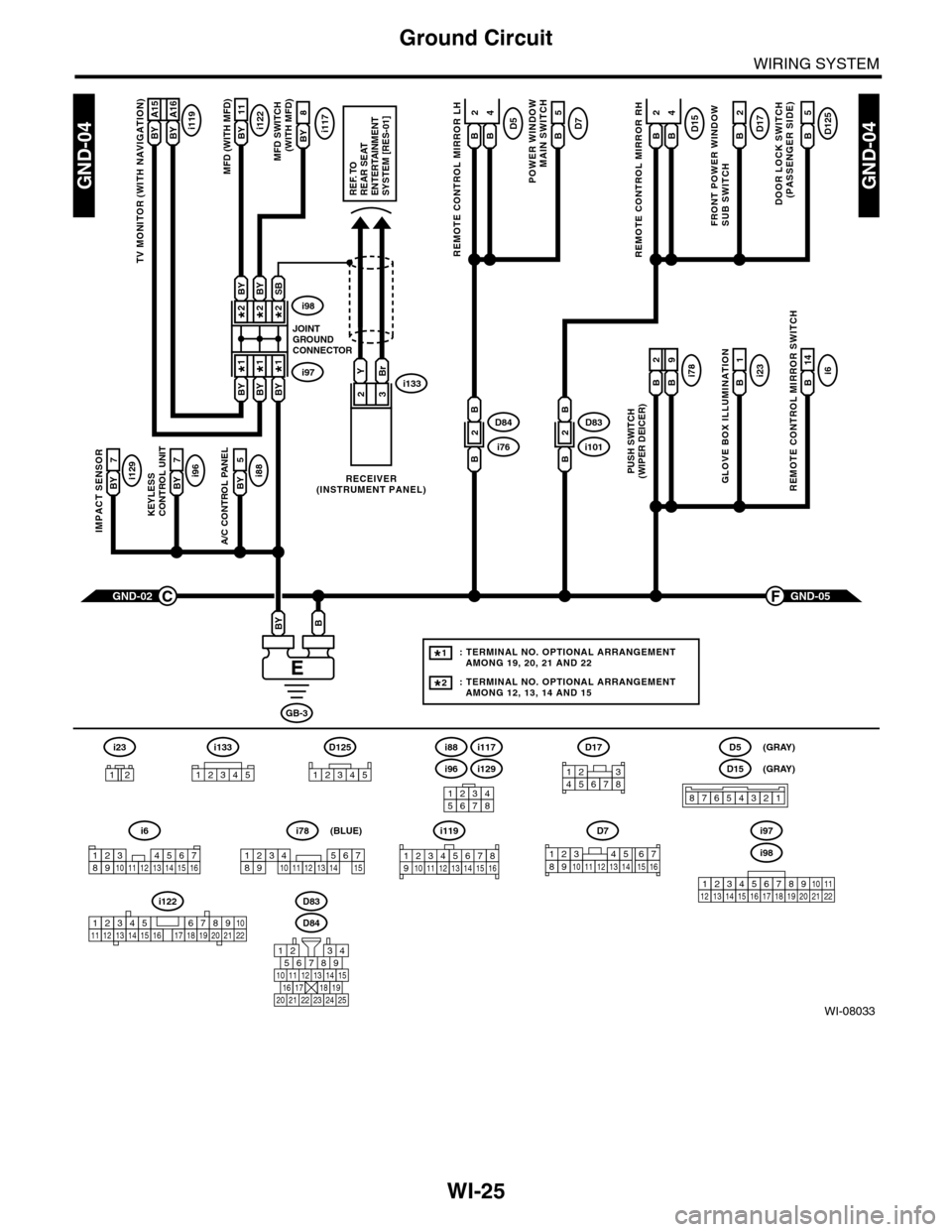
Ground Circuit
WIRING SYSTEM
WI-08033
GND-04GND-04
i117BYi122BY 11
8
A/C CONTROL PANEL
i88BY 5
23
GND-05F
KEYLESS CONTROL UNIT
i96BY 7
IMPACT SENSOR
i129BY 7
TV MONITOR (WITH NAVIGATION)
i119BY A15BY A16
GND-02C
GB-3
BBY
D83
MFD (WITH MFD)MFD SWITCH (WITH MFD)
i96
12345678
i6
42
14
REMOTE CONTROL MIRROR SWITCH
i97i133
i98
JOINTGROUNDCONNECTOR
RECEIVER(INSTRUMENT PANEL)
2*2*
1*1*
2*
1*
BYBi231
GLOVE BOX ILLUMINATION
Bi789
PUSH SWITCH(WIPER DEICER)
B
2
BBYBY
SBBYBY
YBr
REF. TOREAR SEATENTERTAINMENT SYSTEM [RES-01]
: TERMINAL NO. OPTIONAL ARRANGEMENT AMONG 19, 20, 21 AND 22
: TERMINAL NO. OPTIONAL ARRANGEMENT AMONG 12, 13, 14 AND 15
1*
2*
D125
5
DOOR LOCK SWITCH(PASSENGER SIDE)
BD17
2
FRONT POWER WINDOW SUB SWITCH
POWER WINDOW
MAIN SWITCH
BD75
BD15
REMOTE CONTROL MIRROR RH
BB
42D5
REMOTE CONTROL MIRROR LH
BB
i1012D83
B
B
i762D84
B
B
D84
i88
i129
i117
567821943
10
2422 23 25
1112131415161718192021
i98
i97
12345678910111213141516171819202122
D7
12345689101112131514716
D17
12345678
D5
D15
87654321
(GRAY)
(GRAY)
i6
12345678910111213141516
i119
123 8910412 13 14 15 1656711
i133
12345
12345678910111213141516171819202122
i122
i78
123456789101112131415
(BLUE)
i23
12
D125
12345