2009 SUBARU TRIBECA seat heater
[x] Cancel search: seat heaterPage 617 of 2453

SE-7
Front Seat
SEATS
2. Front Seat
A: REMOVAL
CAUTION:
The airbag system is fitted with a backup power
source. After disconnecting the battery ground
cable, the airbag may deploy if you do not wait
for 20 seconds before starting the service of
airbag system.
1. DRIVER’S SEAT
1) Remove the headrest.
2) Tilt the backrest forward, and move the seat for-
ward.
3) Remove the rear leg cover, and remove the two
bolts at the rear side of slide rail.
4) Move the seat backward, remove the front leg
cover, and then remove the 2 bolts at the front side
of the slide rail.
5) Disconnect the ground cable from battery, and
wait for more than 20 seconds before starting work.
6) Disconnect the connector under the seat.
•Seat belt buckle switch connector
•Seat position sensor connector
•Side airbag connector
•Seat heater connector
•Power seat connector
7) Remove the seat from vehicle.
2. PASSENGER’S SEAT
CAUTION:
Refer to “CAUTION” of “General Description”
before starting the work.
1) Remove the headrest.
2) Tilt the backrest forward, and move the seat for-
ward.
3) Remove the rear leg cover, and remove the bolt
at the rear side of the slide rail.
4) Move the seat backward, remove the front leg
cover, and then remove the bolt at the front side of
the slide rail.
5) Disconnect the ground cable from battery, and
wait for more than 20 seconds before starting work.
6) Disconnect all the connectors of connector hold-
er in the backside of seat cushion.
•Harness connector of occupant detection control
module
•Side airbag connector
•Power seat connector
•Seat heater connector
7) Remove the seat belt anchor cover.
NOTE:
Tilt the seat back all the way to provide workspace.
8) Remove the seat from vehicle.
B: INSTALLATION
Install in the reverse order of removal.
NOTE:
Tighten the slide rail installing bolt gradually in sev-
eral steps to the specified torque in the order as
shown in the figure.
CAUTION:
After installing the driver’s seat, use the Subaru
Select Monitor to confirm that the seat position
sensor LH is operating properly.
OPERATION, Subaru Select Monitor.>
Tightening torque:
Refer to “COMPONENT” of “General Descrip-
tion”.
C: DISASSEMBLY
1. DRIVER’S SEAT
1) Remove the seat from vehicle.
2) Remove the clip (A) and straps (B) on the back
of seat cushion.
3) Disconnect the following connectors from the
backside of seat cushion.
•Side airbag
•Seat position sensor
•Seat heater
•Power seat
•Seat belt
SE-00479
(1)
(3)
(4)
(2)
(B)(A)
SE-00643
Page 629 of 2453
SE-19
Seat Heater System
SEATS
5. Seat Heater System
A: REMOVAL
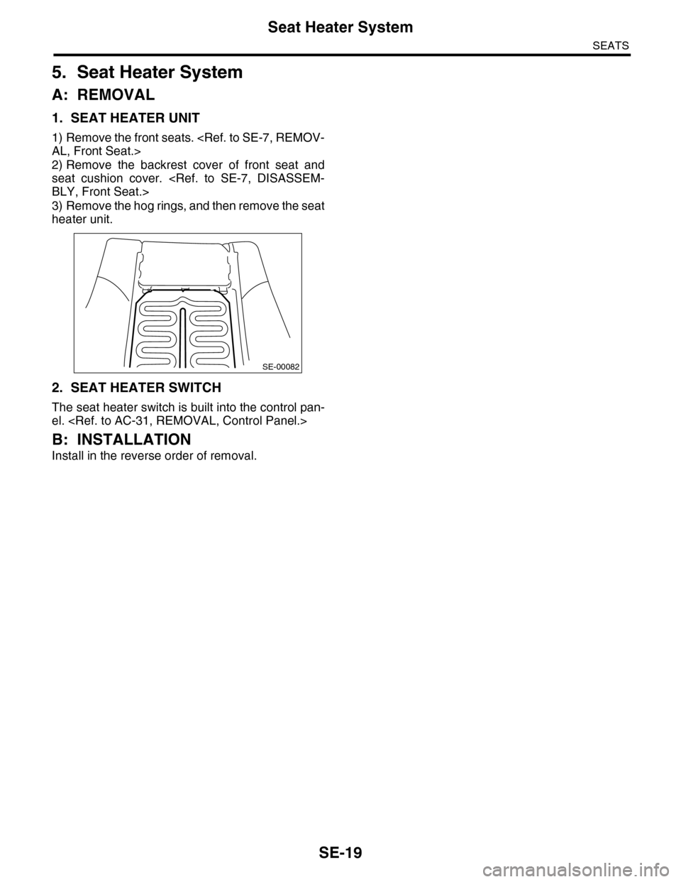
1. SEAT HEATER UNIT
1) Remove the front seats.
2) Remove the backrest cover of front seat and
seat cushion cover.
3) Remove the hog rings, and then remove the seat
heater unit.
2. SEAT HEATER SWITCH
The seat heater switch is built into the control pan-
el.
B: INSTALLATION
Install in the reverse order of removal.
SE-00082
Page 630 of 2453
SE-20
Seat Heater System
SEATS
Page 2304 of 2453
WI-20
Power Supply Circuit
WIRING SYSTEM
No. Load
MB-1 Fail safe relay
MB-2 VDC control module
MB-5 Mirror heater relay
Rear defogger
MB-6 Body integrated unit
MB-8 PWM controller
MB-9 ECM
MB-14 OP connector
Lighting switch
MB-15 Combination meter
MB-16 Headlight RH
MB-17 Headlight LH
MB-18 OP connector
Daytime running light control module
MB-19 Horn
MB-20 Horn
MB-21 Body integrated unit
MB-22 Ignition relay
Main relay
MB-23 Main relay
MB-24 Electronic throttle control relay
MB-25 Fuel pump relay
MB-26 TCM
MB-27 ECM
Data link connector
MB-28 Key warning switch
Tu r n s i g n a l & h a z a r d u n i t
Body integrated unit
MB-29 Auto A/C control module
Spot map light
Va n i t y m i r r o r i l l u m i n a t i o n l i g h t R H
Handle light LH
Handle light RH
Foot light (Driver’s seat)
Foot light (Passenger’s seat)
Home link
Body integrated unit
MB-30 Power window circuit breaker
MB-31 F/B fuse No. 16
MB-32 ALT-1
ECM
Par king light switch
MB-33 Blower fan relay
MB-34 Accessory relay 2
Va c u u m p u m p r e l ay
ALT-1 ECM
FB-1 Trailer connector
FB-3 Stop light & brake switch
Stop light switch
FB-4 Mirror heater relay
Wiper deicer relay
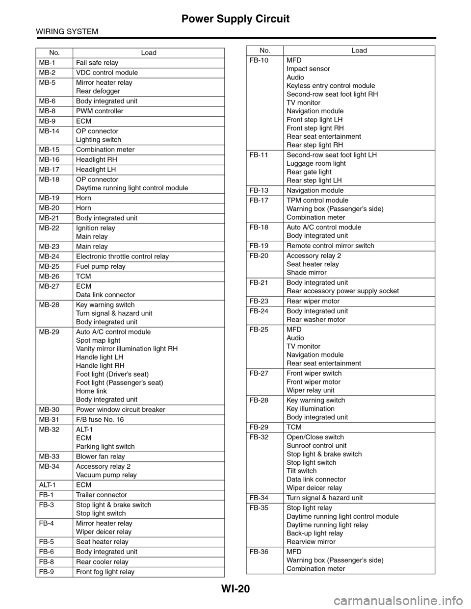
FB-5 Seat heater relay
FB-6 Body integrated unit
FB-8 Rear cooler relay
FB-9 Front fog light relay
FB-10 MFD
Impact sensor
Audio
Keyless entr y control module
Second-row seat foot light RH
TV monitor
Navigation module
Fr o n t s te p li gh t LH
Fr o n t s te p li gh t RH
Rear seat entertainment
Rear step light RH
FB-11 Second-row seat foot light LH
Luggage room light
Rear gate light
Rear step light LH
FB-13 Navigation module
FB-17 TPM control module
War ning box (Passenger’s side)
Combination meter
FB-18 Auto A/C control module
Body integrated unit
FB-19 Remote control mirror switch
FB-20 Accessory relay 2
Seat heater relay
Shade mirror
FB-21 Body integrated unit
Rear accessory power supply socket
FB-23 Rear wiper motor
FB-24 Body integrated unit
Rear washer motor
FB-25 MFD
Audio
TV monitor
Navigation module
Rear seat entertainment
FB-27 Front wiper switch
Fr o n t wi p er mo t or
Wiper relay unit
FB-28 Key warning switch
Key illumination
Body integrated unit
FB-29 TCM
FB-32 Open/Close switch
Sunroof control unit
Stop light & brake switch
Stop light switch
Tilt switch
Data link connector
Wiper deicer relay
FB-34 Turn signal & hazard unit
FB-35 Stop light relay
Daytime running light control module
Daytime running light relay
Back-up light relay
Rearview mirror
FB-36 MFD
War ning box (Passenger’s side)
Combination meter
No. Load
Page 2306 of 2453
WI-22
Ground Circuit
WIRING SYSTEM
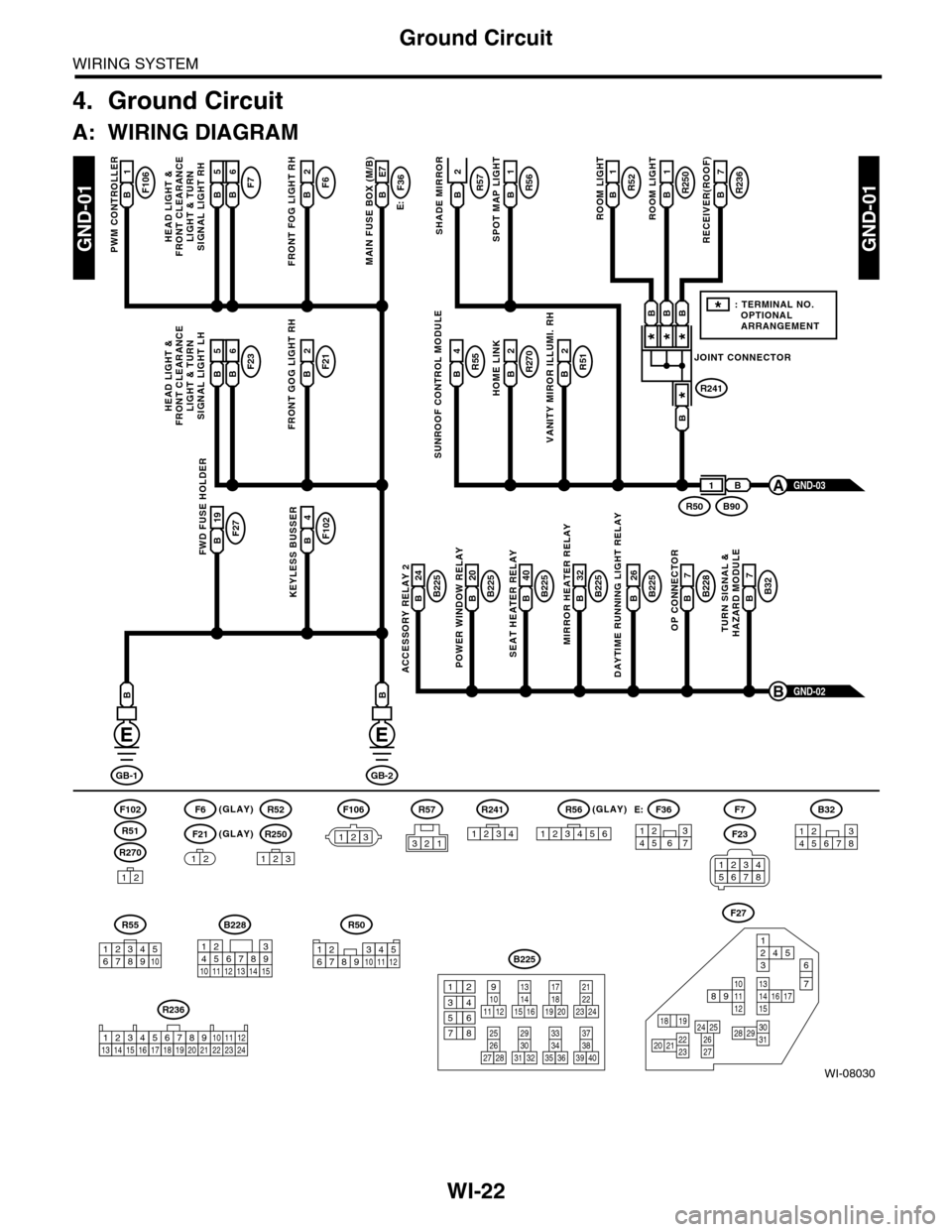
4. Ground Circuit
A: WIRING DIAGRAM
WI-08030
GND-01GND-01
F106B1
PWM CONTROLLER
F6(GLAY)(GLAY)
(GLAY)
F102
R270
F21
F7F6B2
FRONT FOG LIGHT RH
E:
F36B E7
MAIN FUSE BOX (M/B)
R55B4R51B2
VANITY MIROR ILLUMI. RH
R270B2
HOME LINK
R52B1
1
ROOM LIGHT
R250R57B1
ROOM LIGHT
R236B7
RECEIVER(ROOF)SHADE MIRROR
B225B 26
DAYTIME RUNNING LIGHT RELAY
F27B 19FWD FUSE HOLDER
F102B4
KEYLESS BUSSERB225B 24
ACCESSORY RELAY 2
B225B 40
SEAT HEATER RELAY
B225B 20
POWER WINDOW RELAY
B228B7
OP CONNECTOR
B32B7
TURN SIGNAL &HAZARD MODULE
B225B 32
MIRROR HEATER RELAY
GND-02B
GB-1
B
GB-2
B
B
12
12
R52
R250
123
F7
F23
R57
B228
131415
123456789101112
F27
13141516 17
27
24 252620 212223
29303128
89101112
12534
7
6
1918
B225
13141516
17
27
24
2526
20
212223
293031283235
33343738393640
8
9101112
12
534
761918
B32
12345678
SUNROOF CONTROL MODULE
HEAD LIGHT &FRONT CLEARANCELIGHT & TURNSIGNAL LIGHT RH
GND-03A
R51
234510 111678912
R50
F106
123
B A16B5B6
F23F21B2
FRONT GOG LIGHT RH
HEAD LIGHT &FRONT CLEARANCELIGHT & TURNSIGNAL LIGHT LH
B A16B5B6
R56B
SPOT MAP LIGHT
JOINT CONNECTOR
R241
***
*
B90R50
B
B
BBB
1
*: TERMINAL NO. OPTIONAL ARRANGEMENT
123
R56
1234561234567
F36E:
R55
12346789510
R241
1234
R236
123 8910413 14 15 1656711121718192021222324
2
34561278
Page 2369 of 2453
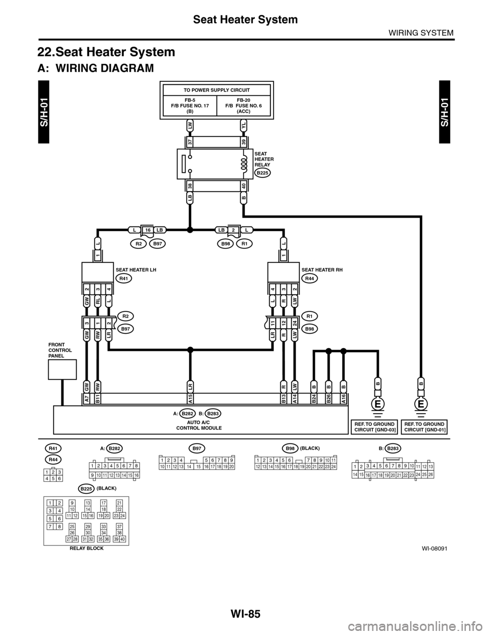
WI-85
Seat Heater System
WIRING SYSTEM
22.Seat Heater System
A: WIRING DIAGRAM
WI-08091
S/H-01S/H-01LW
FB-5F/B FUSE NO. 17(B)
TO POWER SUPPLY CIRCUIT
YL
FB-20F/B FUSE NO. 6(ACC)
R41
SEATHEATERRELAY
LB
38
B
40
B225
3739
B
REF. TO GROUNDCIRCUIT [GND-01]
B
REF. TO GROUNDCIRCUIT [GND-03]
L
1
GW 2RL 3L
GWRWLR
4
312
SEAT HEATER LH
FRONTCONTROLPANEL
RELAY BLOCK
R41
R2
B97
R44
B225
129101112
13141516
17181920
21222324
25262728
29303132
33343536
37383940
345678
L
1
L4R3LW
LRRLW
2
111224
SEAT HEATER RH
R44
R1
B98
LLB
B97R2
LBL
R1B98
GWRWLRRLWBB
A7B11A15B13A14B24A16
B282A:B283B:
AUTO A/C CONTROL MODULE
B
B26
B283A:
345678910
16 17 18 19 20
121112132425262122231415
B282B:
12345678
910 1112 1314 1516
B98(BLACK)
(BLACK)
123456 78910 1112 13 16 1714 15 18 19 2021222324
B97
12345678910 11 12 13 16 17 18 19 201415123456
162
Page 2386 of 2453
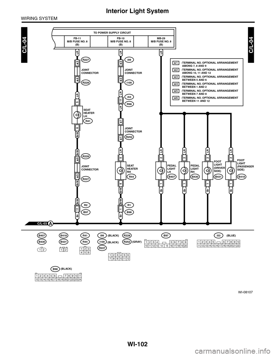
WI-102
Interior Light System
WIRING SYSTEM
WI-08107
C/L-04C/L-04
TO POWER SUPPLY CIRCUIT
MB-29M/B FUSE NO. 8(B)
FB-10M/B FUSE NO. 8(B)
FOOT LIGHT(PASSENGERSIDE)
B418
C/L-03A
:TERMINAL NO. OPTIONAL ARRANGEMENT AMONG 7, 8 AND 9:TERMINAL NO. OPTIONAL ARRANGEMENT AMONG 10, 11 AND 12
1*
2*
:TERMINAL NO. OPTIONAL ARRANGEMENT BETWEEN 5 AND 63*
:TERMINAL NO. OPTIONAL ARRANGEMENT BETWEEN 7 AND 85*
:TERMINAL NO. OPTIONAL ARRANGEMENT BETWEEN 11 AND 126*
:TERMINAL NO. OPTIONAL ARRANGEMENT BETWEEN 1 AND 24*
2
LR
1
Br
FOOTLIGHT(DRIVER SIDE)
B431
2
LR
1
Br
PEDALLIGHTRH
B430
2
LR
1
Br
PEDALLIGHTLH
B407
2
LR
1
Br
SEATHEATERRH
R44
R1
B98
5
LR
6
BrW
LRLR
R98
i53
JOINTCONNECTOR
i99
i100
2*
2*
JOINTCONNECTOR
R252
1*
1*
11
LR
LR
1
Br
BrW
FB-11M/B FUSE NO. 8(B)
SEATHEATERLH
R41
R2
B97
5
LR
6
BrW
BrW
BrW
LR
JOINTCONNECTOR
R227
R228
3*
4*
JOINTCONNECTOR
R228
R227
6*
5*
11
Br
BrW
R41
R44
B98(BLACK)
123456 78910 1112 13 16 1714 15 18 19 2021222324
B97
12345678910 11 12 13 16 17 18 19 201415123456
123 8910411 12 13 14 15 16567171819202122
i53(BLUE)
B431
B418
12
B430
B407
12
123456789101112
i100(BLACK)
R227
i99(BLACK)
R252(GRAY)
R228
Page 2438 of 2453
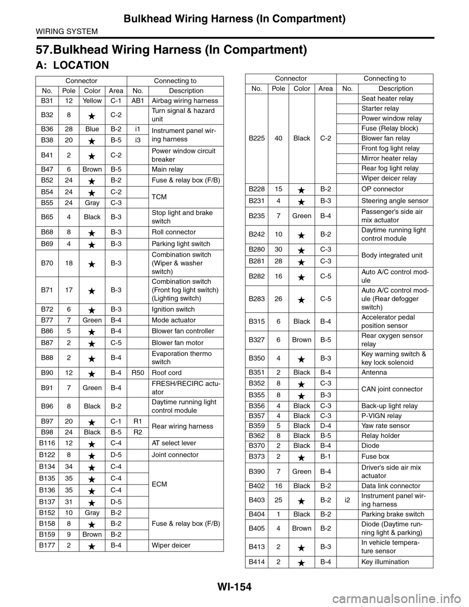
WI-154
Bulkhead Wiring Harness (In Compartment)
WIRING SYSTEM
57.Bulkhead Wiring Harness (In Compartment)
A: LOCATION
Connector Connecting to
No. Pole Color Area No. Description
B31 12 Yellow C-1 AB1 Airbag wiring harness
B32 8 C-2Tu r n s i g n a l & h a z a r d
unit
B36 28 Blue B-2 i1Instrument panel wir-
ing harnessB38 20 B-5 i3
B41 2 C-2Powe r w in d ow ci r cu i t
breaker
B47 6 Brown B-5 Main relay
B52 24 B-2 Fuse & relay box (F/B)
B54 24 C-2TCMB55 24 Gray C-3
B65 4 Black B-3Stop light and brake
switch
B68 8 B-3 Roll connector
B69 4 B-3 Parking light switch
B70 18 B-3
Combination switch
(Wiper & washer
switch)
B71 17 B-3
Combination switch
(Front fog light switch)
(Lighting switch)
B72 6 B-3 Ignition switch
B77 7 Green B-4 Mode actuator
B86 5 B-4 Blower fan controller
B87 2 C-5 Blower fan motor
B88 2 B-4Evaporation thermo
switch
B90 12 B-4 R50 Roof cord
B91 7 Green B-4FRESH/RECIRC actu-
ator
B96 8 Black B-2Daytime running light
control module
B97 20 C-1 R1Rear wiring harnessB98 24 Black B-5 R2
B116 12 C-4 AT select lever
B122 8 D-5 Joint connector
B134 34 C-4
ECMB135 35 C-4
B136 35 C-4
B137 31 D-5
B152 10 Gray B-2
Fuse & relay box (F/B)B158 8 B-2
B159 9 Brown B-2
B177 2 B-4 Wiper deicer
B225 40 Black C-2
Seat heater relay
Starter relay
Pow er w i n dow r el ay
Fuse (Relay block)
Blower fan relay
Fr o nt fog li g ht r el ay
Mirror heater relay
Rear fog light relay
Wiper deicer relay
B228 15 B-2 OP connector
B231 4 B-3 Steering angle sensor
B235 7 Green B-4Passenger’s side air
mix actuator
B242 10 B-2Daytime running light
control module
B280 30 C-3Body integrated unitB281 28 C-3
B282 16 C-5Auto A/C control mod-
ule
B283 26 C-5
Auto A/C control mod-
ule (Rear defogger
switch)
B315 6 Black B-4Accelerator pedal
position sensor
B327 6 Brown B-5Rear oxygen sensor
relay
B350 4 B-3Key war ning switch &
key lock solenoid
B351 2 Black B-4 Antenna
B352 8 C-3CAN joint connectorB355 8 B-3
B356 4 Black C-3 Back-up light relay
B357 4 Black C-3 P-VIGN relay
B359 5 Black D-4 Yaw rate sensor
B362 8 Black B-5 Relay holder
B370 2 Black B-4 Diode
B373 2 B-1 Fuse box
B390 7 Green B-4Driver’s side air mix
actuator
B402 16 Black B-2 Data link connector
B403 25 B-2 i2Instrument panel wir-
ing harness
B404 1 Black B-2 Parking brake switch
B405 4 Brown B-2Diode (Daytime run-
ning light & parking)
B413 2 B-3In vehicle tempera-
ture sensor
B414 2 B-4 Key illumination
Connector Connecting to
No. Pole Color Area No. Description