2009 SUBARU TRIBECA manual transmission
[x] Cancel search: manual transmissionPage 959 of 2453
![SUBARU TRIBECA 2009 1.G Service Workshop Manual TPM(diag)-9
Subaru Select Monitor
TIRE PRESSURE MONITORING SYSTEM (DIAGNOSTICS)
2. DATA DISPLAY
1) On the «Main Menu» display screen, select the {Each System Check} and press the [YES] key.
2) On th SUBARU TRIBECA 2009 1.G Service Workshop Manual TPM(diag)-9
Subaru Select Monitor
TIRE PRESSURE MONITORING SYSTEM (DIAGNOSTICS)
2. DATA DISPLAY
1) On the «Main Menu» display screen, select the {Each System Check} and press the [YES] key.
2) On th](/manual-img/17/7322/w960_7322-958.png)
TPM(diag)-9
Subaru Select Monitor
TIRE PRESSURE MONITORING SYSTEM (DIAGNOSTICS)
2. DATA DISPLAY
1) On the «Main Menu» display screen, select the {Each System Check} and press the [YES] key.
2) On the «System Selection Menu» display screen, select the {Tire Pressure Monitor} and press the [YES]
key.
3) Press the [YES] key after the {Tire Pressure Monitor} is displayed.
4) On the «Tire pressure monitor diagnosis» display screen, select the {Data Display}, and then press the
[YES] key, then necessary data will be displayed.
•A list of the support data is shown in the following table.
3. CLEAR MEMORY
1) On the «Main Menu», select the {2. Each Sys-
tem Check} and press the [YES] key.
2) On the «System Selection Menu» display
screen, select the {Tire Pressure Monitor} and
press the [YES] key.
3) Press the [YES] key after the {Tire Pressure
Monitor} is displayed.
4) On the «Tire Pressure Monitor Diagnosis» dis-
play screen, select the {Memory Clear} and press
the [YES] key.
5) When «Done» and «Turn ignition switch OFF»
are shown on the display screen, turn the Subaru
Select Monitor and ignition switch to OFF.
NOTE:
For details concerning operation procedure, refer
to the “SUBARU SELECT MONITOR OPERATION
MANUAL”.
4. REGISTER TRANSMITTER ID
Perform the procedures below to register the trans-
mitter.
•Transmitter replaced.
•Switched the position of the transmitter (rotated
tires)
•Replaced the tire pressure monitoring control
module.
NOTE:
•If registration of the transmitter ID is not possible
after 2 attempts, replace the tire pressure monitor-
ing control module.
REMOVAL, Tire Pressure Monitoring System.>
•If the ignition switch and Subaru Select Monitor
power are turned OFF while registering the trans-
mitter, or if registration is not possible for more than
5 minutes, the registration mode is cancelled.
•When rotating tires, there is no affect on the per-
formance or functions of the tire pressure monitor-
ing control module even if the transmitter (ID) is not
registered, however, the tire position displayed on
the Subaru Select Monitor will be incorrect.
1) Adjust all tire pressures to the specifications.
NOTE:
Refer to the tire caution label on the driver's side
door for the correct tire pressure.
Display Contents to be monitored Unit of measure
FR FN Code
LEARN, LOW BAT, OFF, WAKE, RE ME, NOR-
MAL
LEARN: Transmitted transmitter ID using the transmit-
ter registration tool
LOW BAT: Transmitter battery voltage running low
OFF: Transmitter function stops (no data transmission)
RE ME: Tire air changes ±8.4 kPa
WA K E : S t a r t ed tr an sm it t i ng da t a f r o m a s t op p ed st a te
NORMAL: Conditions other than above
FL FN Code
RR FN Code
RL FN Code
FR tire pressureVa l u e c o nve r t e d t o t i r e p r e s s u r e f r o m d a t a d e l i v -
ered from transmitter is displayed.
(It may be different from values measured by the
direct contact meter.)
kPa, psig, mmHg, inHg
FL tire pressurekPa, psig, mmHg, inHg
RR tire pressurekPa, psig, mmHg, inHg
RL tire pressurekPa, psig, mmHg, inHg
Ve h i c l e S p e e dVe h i c l e s p e e d s i g n a l w h i c h i s i n p u t i n c o n t r o l
module.km/h, MPH
Pressure warning Threshold where tire pressure warning light lights kPa, psig, mmHg, inHg
Return pressureThreshold where tire pressure warning light goes
outkPa, psig, mmHg, inHg
Page 2018 of 2453
5AT-2
General Description
AUTOMATIC TRANSMISSION
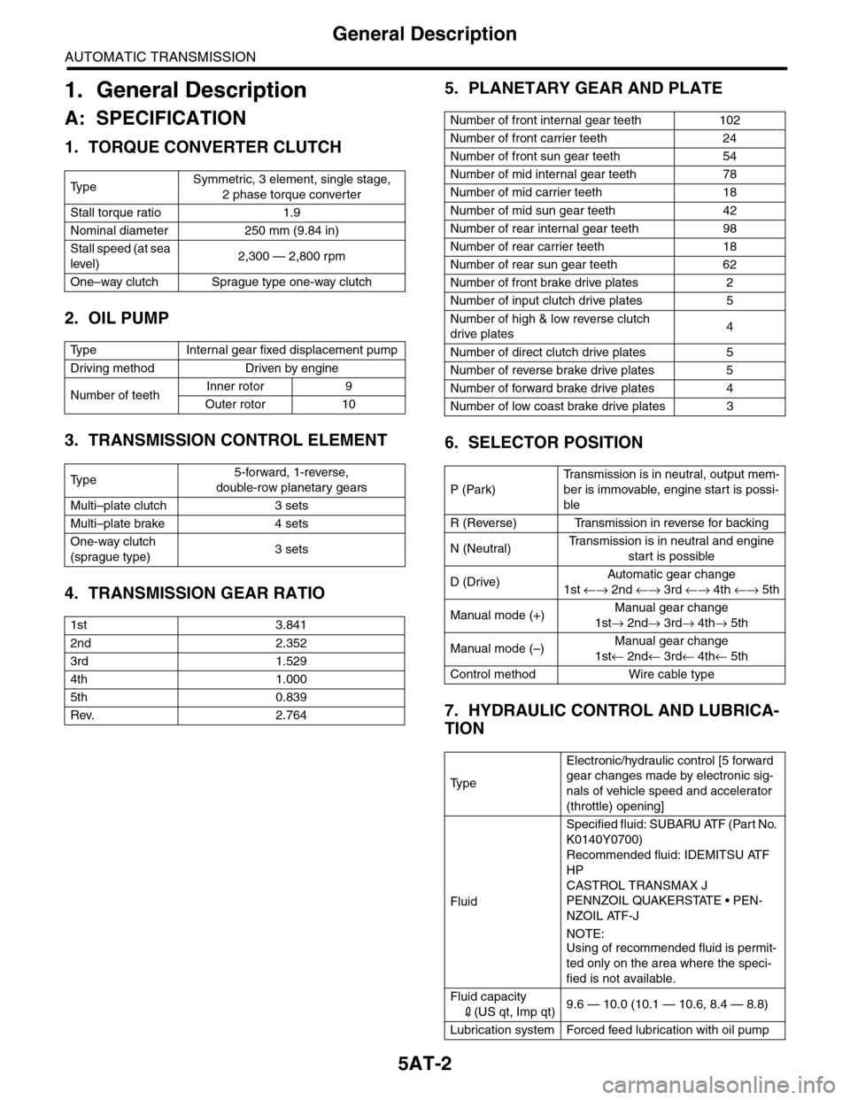
1. General Description
A: SPECIFICATION
1. TORQUE CONVERTER CLUTCH
2. OIL PUMP
3. TRANSMISSION CONTROL ELEMENT
4. TRANSMISSION GEAR RATIO
5. PLANETARY GEAR AND PLATE
6. SELECTOR POSITION
7. HYDRAULIC CONTROL AND LUBRICA-
TION
Ty p eSymmetric, 3 element, single stage,
2 phase torque converter
Stall torque ratio 1.9
Nominal diameter 250 mm (9.84 in)
Stall speed (at sea
level)2,300 — 2,800 rpm
One–way clutch Sprague type one-way clutch
Ty p e I n t e r n a l g e a r f i x e d d i s p l a c e m e n t p u m p
Driving method Driven by engine
Number of teethInner rotor 9
Outer rotor 10
Ty p e5-forward, 1-reverse,
double-row planetary gears
Multi–plate clutch 3 sets
Multi–plate brake 4 sets
One-way clutch
(sprague type)3 sets
1st 3.841
2nd 2.352
3rd 1.529
4th 1.000
5th 0.839
Rev. 2.764
Number of front internal gear teeth 102
Number of front carrier teeth 24
Number of front sun gear teeth 54
Number of mid internal gear teeth 78
Number of mid carrier teeth 18
Number of mid sun gear teeth 42
Number of rear internal gear teeth 98
Number of rear carrier teeth 18
Number of rear sun gear teeth 62
Number of front brake drive plates 2
Number of input clutch drive plates 5
Number of high & low reverse clutch
drive plates4
Number of direct clutch drive plates 5
Number of reverse brake drive plates 5
Number of forward brake drive plates 4
Number of low coast brake drive plates 3
P (Park)
Tr a n s m i s s i o n i s i n n e u t r a l , o u t p u t m e m -
ber is immovable, engine start is possi-
ble
R (Reverse) Transmission in reverse for backing
N (Neutral)Tr a n s m i s s i o n i s i n n e u t r a l a n d e n g i n e
start is possible
D (Drive)Automatic gear change
1st ←→ 2nd ←→ 3rd ←→ 4th ←→ 5th
Manual mode (+)Manual gear change
1st→ 2nd→ 3rd→ 4th→ 5th
Manual mode (–)Manual gear change
1st← 2nd← 3rd← 4th← 5th
Control method Wire cable type
Ty p e
Electronic/hydraulic control [5 forward
gear changes made by electronic sig-
nals of vehicle speed and accelerator
(throttle) opening]
Fluid
Specified fluid: SUBARU ATF (Part No.
K0140Y0700)
Recommended fluid: IDEMITSU ATF
HP
CASTROL TRANSMAX J
PENNZOIL QUAKERSTATE • PEN-
NZOIL ATF-J
NOTE:
Using of recommended fluid is permit-
ted only on the area where the speci-
fied is not available.
Fluid capacity
2(US qt, Imp qt)9.6 — 10.0 (10.1 — 10.6, 8.4 — 8.8)
Lubrication system Forced feed lubrication with oil pump
Page 2030 of 2453
5AT-14
General Description
AUTOMATIC TRANSMISSION
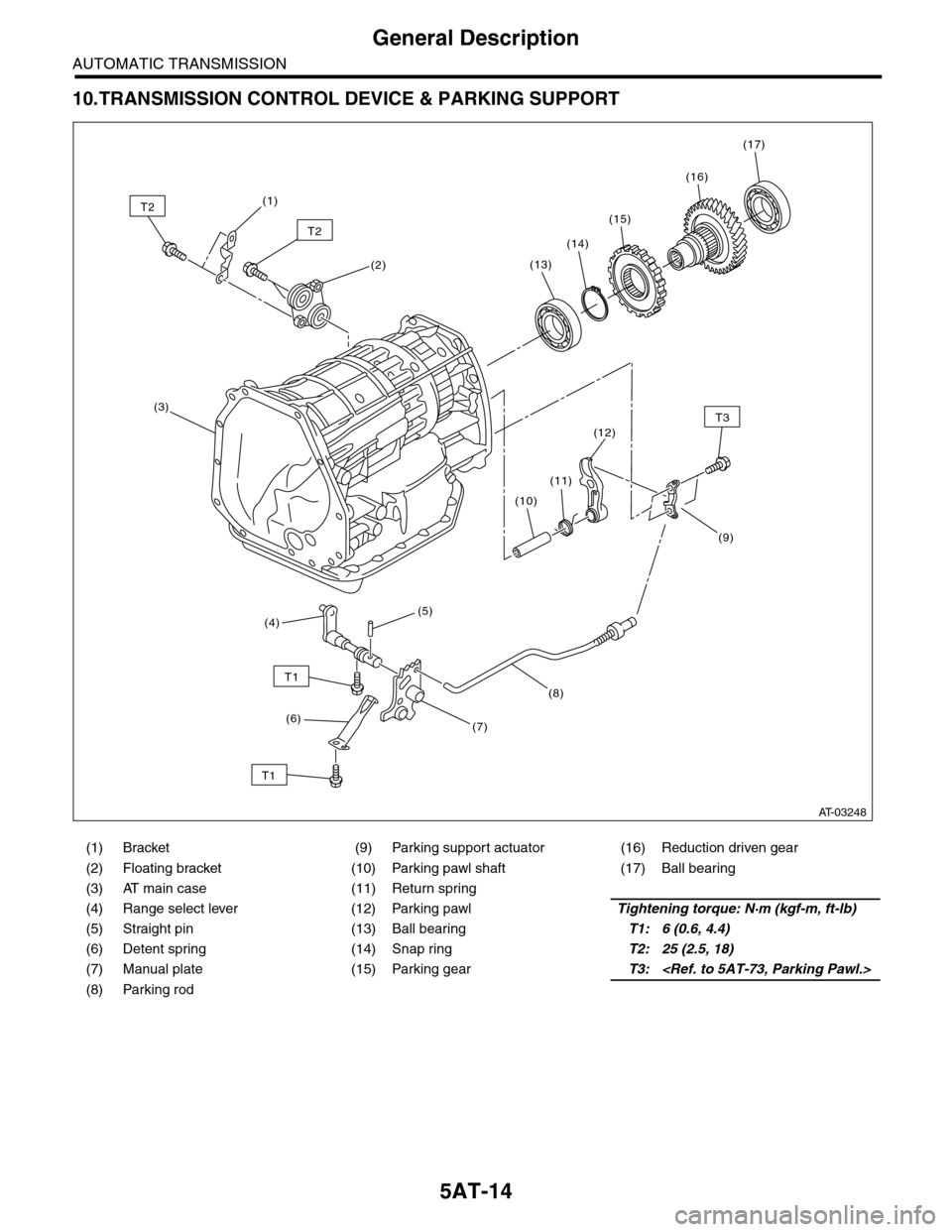
10.TRANSMISSION CONTROL DEVICE & PARKING SUPPORT
(1) Bracket (9) Parking support actuator (16) Reduction driven gear
(2) Floating bracket (10) Parking pawl shaft (17) Ball bearing
(3) AT main case (11) Return spring
(4) Range select lever (12) Parking pawlTightening torque: N·m (kgf-m, ft-lb)
(5) Straight pin (13) Ball bearingT1: 6 (0.6, 4.4)
(6) Detent spring (14) Snap ringT2: 25 (2.5, 18)
(7) Manual plate (15) Parking gearT3:
(8) Parking rod
T2
T2
T3
T1
T1
(1)
(2)
(3)
(10)
(11)
(8)
(7)
(5)(4)
(6)
(12)
(13)
(14)
(15)
(16)
(17)
(9)
AT-03248
Page 2045 of 2453
5AT-29
Road Test
AUTOMATIC TRANSMISSION
4. Road Test
A: INSPECTION
1. GENERAL PRECAUTION
Road tests should be conducted to properly diag-
nose the condition of automatic transmission.
NOTE:
When performing the test, do not exceed posted
speed limit.
2. D RANGE SHIFT FUNCTION
Check shifting between 1st ←→ 2nd ←→ 3rd ←→
4th ←→ 5th while driving on normal city streets.
3. D RANGE SHIFT SHOCK
Check the shock level when shifting up during nor-
mal driving.
4. KICK–DOWN FUNCTION
Check kick–down for each gear. Check the shock
level during kick–down at the same time.
5. ENGINE BRAKE OPERATION
•Check the 4th gear engine brake when shifting
down from 5th to 4th range while driving in 5th gear
of manual mode [50 to 60 km/h (31 to 37 MPH)].
•Check the 3rd gear engine brake when shifting
down from 4th to 3rd range while driving in 4th gear
of manual mode [50 — 60 km/h (31 — 37 MPH)].
•Check the 2nd gear engine brake when shifting
down from 3rd to 2nd range while driving in 3rd
gear of manual mode [40 — 50 km/h (25 — 31
MPH)].
•Check the 1st gear engine brake when shifting
down from 2nd to 1st range while driving in 2nd
gear of manual mode [20 — 30 km/h (12 — 19
MPH)].
6. P RANGE OPERATION
Stop the vehicle on an uphill grade of 5% or more
and shift to the “P” range. Check that the vehicle
does not move when the parking brake is released.
7. NOISE AND VIBRATION
Check for noise and vibration while driving and dur-
ing shifting.
8. OIL LEAKAGE
After the driving test, inspect for oil leaks from the
transmission body.
Page 2046 of 2453
5AT-30
Stall Test
AUTOMATIC TRANSMISSION
5. Stall Test
A: INSPECTION
NOTE:
The stall test is extremely important in diagnosing
the condition of an automatic transmission and en-
gine. It should be conducted to measure the engine
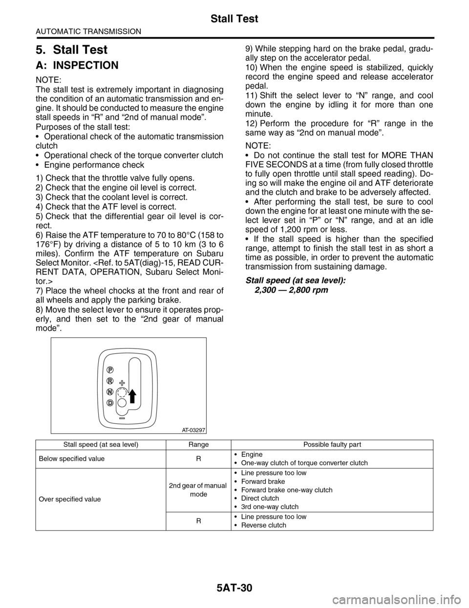
stall speeds in “R” and “2nd of manual mode”.
Purposes of the stall test:
•Operational check of the automatic transmission
clutch
•Operational check of the torque converter clutch
•Engine performance check
1) Check that the throttle valve fully opens.
2) Check that the engine oil level is correct.
3) Check that the coolant level is correct.
4) Check that the ATF level is correct.
5) Check that the differential gear oil level is cor-
rect.
6) Raise the ATF temperature to 70 to 80°C (158 to
176°F) by driving a distance of 5 to 10 km (3 to 6
miles). Confirm the ATF temperature on Subaru
Select Monitor.
tor.>
7) Place the wheel chocks at the front and rear of
all wheels and apply the parking brake.
8) Move the select lever to ensure it operates prop-
erly, and then set to the “2nd gear of manual
mode”.
9) While stepping hard on the brake pedal, gradu-
ally step on the accelerator pedal.
10) When the engine speed is stabilized, quickly
record the engine speed and release accelerator
pedal.
11) Shift the select lever to “N” range, and cool
down the engine by idling it for more than one
minute.
12) Perform the procedure for “R” range in the
same way as “2nd on manual mode”.
NOTE:
•Do not continue the stall test for MORE THAN
FIVE SECONDS at a time (from fully closed throttle
to fully open throttle until stall speed reading). Do-
ing so will make the engine oil and ATF deteriorate
and the clutch and brake to be adversely affected.
•After performing the stall test, be sure to cool
down the engine for at least one minute with the se-
lect lever set in “P” or “N” range, and at an idle
speed of 1,200 rpm or less.
•If the stall speed is higher than the specified
range, attempt to finish the stall test in as short a
time as possible, in order to prevent the automatic
transmission from sustaining damage.
Stall speed (at sea level):
2,300 — 2,800 rpm
AT-03297
Stall speed (at sea level) Range Possible faulty part
Below specified value R•Engine
•One-way clutch of torque converter clutch
Over specified value
2nd gear of manual
mode
•Line pressure too low
•Forward brake
•Forward brake one-way clutch
•Direct clutch
•3rd one-way clutch
R•Line pressure too low
•Reverse clutch
Page 2116 of 2453
5AT-100
Transmission Control Device
AUTOMATIC TRANSMISSION
35.Transmission Control Device
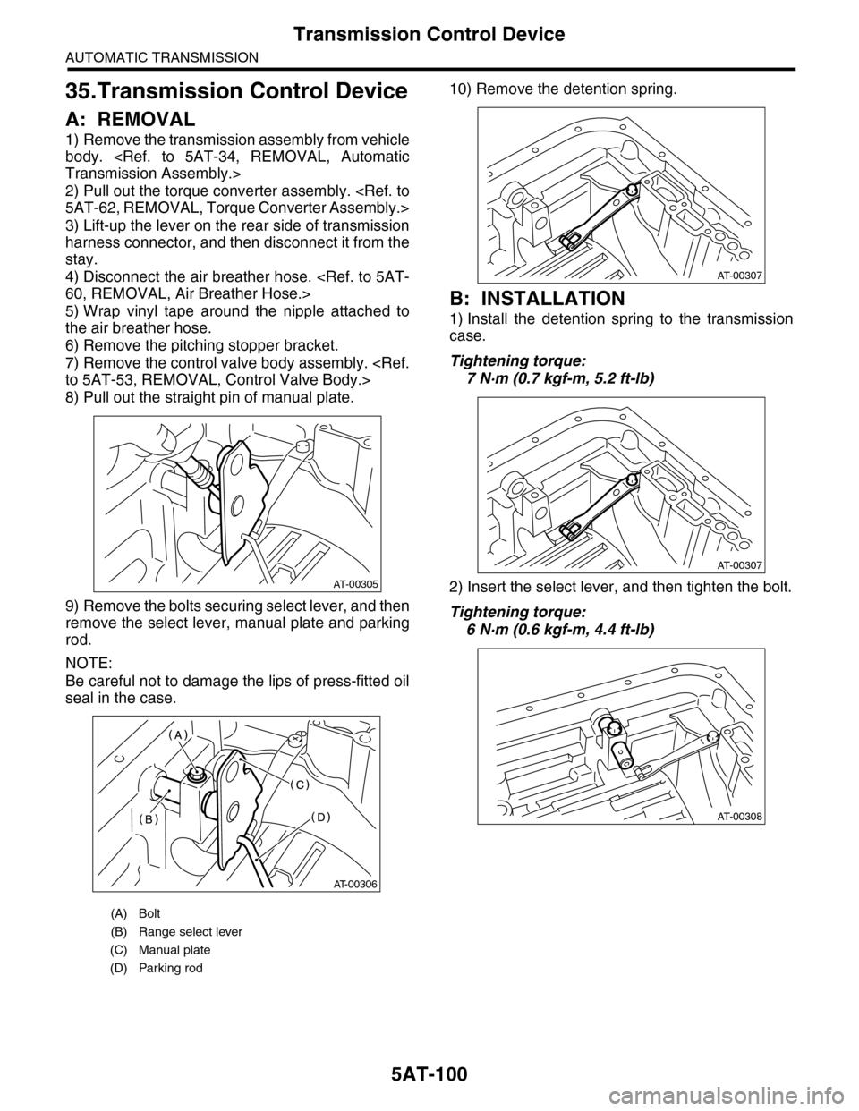
A: REMOVAL
1) Remove the transmission assembly from vehicle
body.
2) Pull out the torque converter assembly.
3) Lift-up the lever on the rear side of transmission
harness connector, and then disconnect it from the
stay.
4) Disconnect the air breather hose.
5) Wrap vinyl tape around the nipple attached to
the air breather hose.
6) Remove the pitching stopper bracket.
7) Remove the control valve body assembly.
8) Pull out the straight pin of manual plate.
9) Remove the bolts securing select lever, and then
remove the select lever, manual plate and parking
rod.
NOTE:
Be careful not to damage the lips of press-fitted oil
seal in the case.
10) Remove the detention spring.
B: INSTALLATION
1) Install the detention spring to the transmission
case.
Tightening torque:
7 N·m (0.7 kgf-m, 5.2 ft-lb)
2) Insert the select lever, and then tighten the bolt.
Tightening torque:
6 N·m (0.6 kgf-m, 4.4 ft-lb)
(A) Bolt
(B) Range select lever
(C) Manual plate
(D) Parking rod
AT-00305
AT-00306
AT-00307
AT-00307
AT-00308
Page 2117 of 2453
5AT-101
Transmission Control Device
AUTOMATIC TRANSMISSION
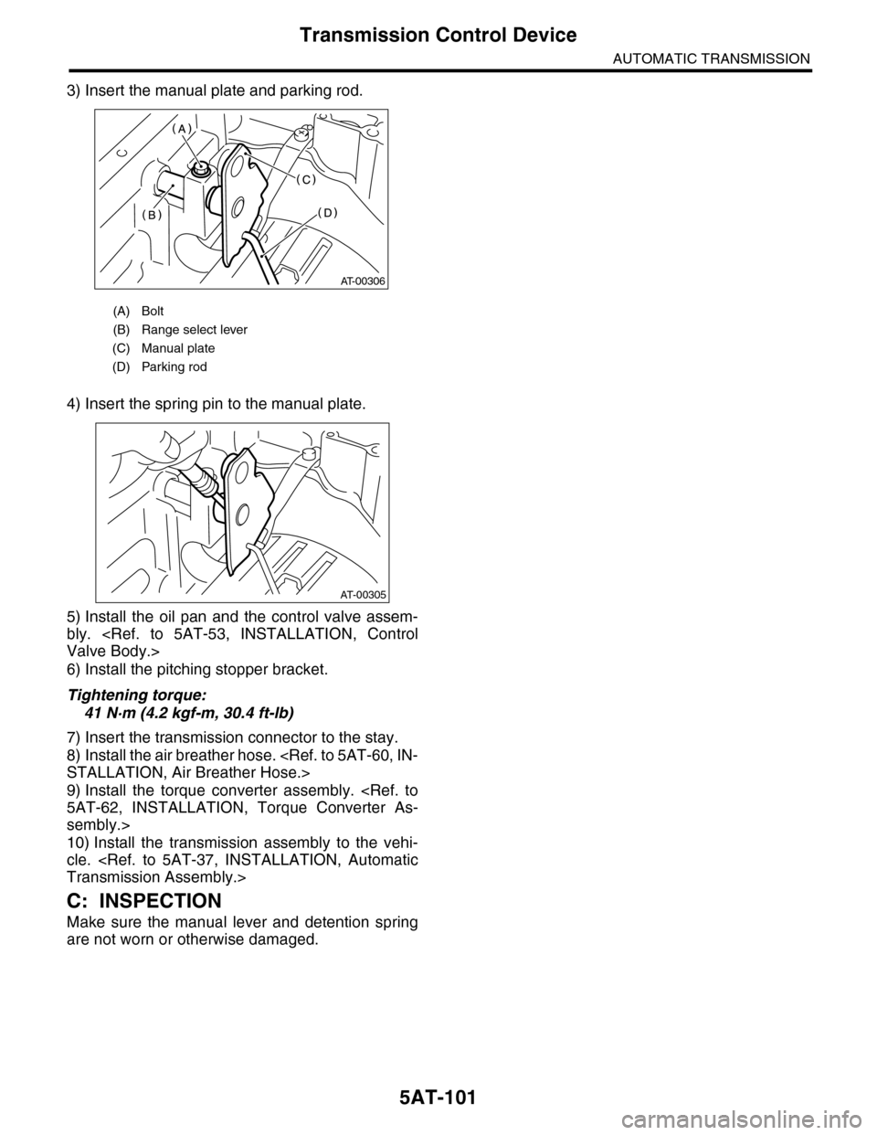
3) Insert the manual plate and parking rod.
4) Insert the spring pin to the manual plate.
5) Install the oil pan and the control valve assem-
bly.
6) Install the pitching stopper bracket.
Tightening torque:
41 N·m (4.2 kgf-m, 30.4 ft-lb)
7) Insert the transmission connector to the stay.
8) Install the air breather hose.
9) Install the torque converter assembly.
sembly.>
10) Install the transmission assembly to the vehi-
cle.
C: INSPECTION
Make sure the manual lever and detention spring
are not worn or otherwise damaged.
(A) Bolt
(B) Range select lever
(C) Manual plate
(D) Parking rod
AT-00306
AT-00305
Page 2121 of 2453
5AT(diag)-4
Check List for Interview
AUTOMATIC TRANSMISSION (DIAGNOSTICS)
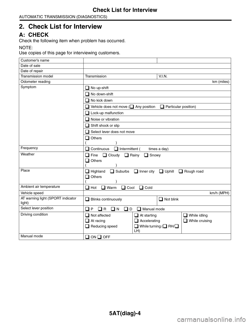
2. Check List for Interview
A: CHECK
Check the following item when problem has occurred.
NOTE:
Use copies of this page for interviewing customers.
Customer’s name
Date of sale
Date of repair
Tr a n s m i s s i o n m o d e l Tr a n s m i s s i o n V. I . N .
Odometer readingkm (miles)
Symptom No up-shift
No down-shift
No kick down
Vehicle does not move ( Any position Particular position)
Lock-up malfunction
Noise or vibration
Shift shock or slip
Select lever does not move
Others
()
Fr e qu e nc y Continuous Intermittent ( times a day)
Weather Fine Cloudy Rainy Snowy
Others
()
Place Highland Suburbs Inner city Uphill Rough road
Others
()
Ambient air temperature Hot Warm Cool Cold
Ve h i c l e s p e e dkm/h (MPH)
AT w a r n i n g l i g h t ( S P O R T i n d i c a t o r
light) Blinks continuously Not blink
Select lever position P R N D Manual mode
Driving condition Not affected
At racing
Reducing speed
At starting
Accelerating
W h i l e t u r n i n g ( R H /
LH)
While idling
While cruising
Manual mode ON OFF