2009 SUBARU OUTBACK battery
[x] Cancel search: batteryPage 104 of 447

2-12Keys and doors
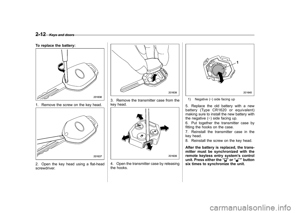
To replace the battery:
1. Remove the screw on the key head.
2. Open the key head using a flat-head
screwdriver.
3. Remove the transmitter case from the
key head.
4. Open the transmitter case by releasing
the hooks.
1) Negative ( �) side facing up
5. Replace the old battery with a new
battery (Type CR1620 or equivalent)
making sure to install the new battery with
the negative ( �) side facing up.
6. Put together the transmitter case by
fitting the hooks on the case.
7. Reinstall the transmitter case in the
key head.
8. Reinstall the screw on the key head.
After the battery is replaced, the trans-
mitter must be synchronized with the
remote keyless entry system ’s control
unit. Press either the “
”or “”button
six times to synchronize the unit.
Page 111 of 447

done during the standby period, the
system will not switch to the surveil-
lance state.–Doors are unlocked using the
remote transmitter. – Any door (including the rear gate
of a Station wagon or the trunk of a
Sedan) is opened. – Ignition switch is turned to the
“ ON ”position.
& Disarming the system
Briefly press the “
”button (for less than
2 seconds) on the remote transmitter. The
driver ’s door will unlock, an electronic
chirp will sound twice, the turn signal
lights will flash twice and the indicator
light will go off.
To unlock all other doors and the rear gate
(Station wagon), briefly press the “
”
button a second time within 5 seconds.
NOTE
If the interval between the first and
second presses of the “
”button (for
unlocking of all of the doors and the
rear gate) is extremely short, the sys-
tem may not respond.
Or the system can be disarmed by the
following method, too. . Insert the key in the door lock of the driver
’s door and turn it to the unlock
position. ! Emergency disarming
If you cannot disarm the system using the
transmitter (i.e. the transmitter is lost,
broken or the transmitter battery is too
weak), you can disarm the system without
using the transmitter.
The system can be disarmed if you turn
the ignition switch from the “LOCK ”to the
“ ON ”position with a registered key.
Insert the key in the door lock of thedriver ’s door and turn it to the unlock
position.
& Valet mode
When you choose the valet mode, the
alarm system does not operate. In valet
mode, the remote transmitter is used only
for locking and unlocking the doors and
rear gate (Station wagon) and panicactivation.
To enter the valet mode, change the
setting of your vehicle ’s alarm system for
deactivation mode. Refer to “Activating
and deactivating the alarm system ”in this
section. The security indicator light will
continue to flash once every 3 seconds
indicating that the system is in the valetmode. To exit valet mode, change the setting of
your vehicle
’s alarm system for activation
mode. Refer to “Activating and deactivat-
ing the alarm system ”in this section.
& Passive arming
When passive arming mode has been
programmed by the dealer, arming of the
system is automatically accomplished
without using the remote transmitter. Note
that in this mode, DOORS MUST BE
MANUALLY LOCKED. ! To enter the passive mode
If you wish to program the passive arming
mode, have it done by your SUBARU
dealer. ! Arming the system
CAUTION
In passive mode, the system will
automatically activate the alarm but
WILL NOT automatically lock the
doors. In order to lock the doors
you must either lock them as in-
dicated in step 4 below or with the
key once they have been closed.
Failure to lock the doors manually
will result in a higher security risk.
1. Turn the ignition switch to the “ON ”
Keys and doors
2-19
– CONTINUED –
Page 120 of 447

2-28Keys and doors
NOTE
If the rear gate cannot be unlocked due
to a discharged battery of the vehicle, a
malfunction in the door locking/unlock-
ing system or other causes, you can
unlock it by manually operating the
rear gate lock release lever.
For the procedure, refer to the “Rear
gate (Station wagon) –if the rear gate
cannot be unlocked ”section in chapter
9. Moonroof (if equipped)
WARNING
Never let anyone ’s hands, arms,
head or any objects protrude from
the moonroof. A person could be
seriously injured if the vehicle stops
suddenly or turns sharply or if the
vehicle is involved in an accident.
To avoid serious personal injury
caused by entrapment, you must
conform to the following instruc-
tions without exception. . Before closing the moonroof,
make sure that no one ’s hands,
arms, head or other objects will
be accidentally caught in themoonroof.
. Before leaving the vehicle, al-
ways remove the key from the
ignition switch for safety and
never allow an unattended child
to remain in the vehicle. Failure
to follow this procedure could
result in injury to a child operat-
ing the moonroof. .
Never try to check the anti-en-
trapment function by deliberately
placing part of your body in themoonroof.
CAUTION
. Do not sit on the edge of the open
moonroof.
. Do not operate the moonroof if
falling snow or extremely cold
conditions have caused it to
freeze shut.
. The anti-entrapment function
does not operate when the moon-
roof is being tilted down. Be sure
to confirm that it is safe to do so
before tilting the moonroof down.
The moonroof has both tilting and slidingfunctions.
The moonroof operates only when the
ignition switch is in the “ON ”position.
Page 126 of 447

Ignition switch
WARNING
. Never turn the ignition switch to
“ LOCK ”while the vehicle is
being driven or towed because
that will lock the steering wheel,
preventing steering control. And
when the engine is turned off, it
takes a much greater effort than
usual to steer.
. Before leaving the vehicle, al-
ways remove the key from the
ignition switch for safety and
never allow an unattended child
to remain in the vehicle. Failure
to follow this procedure could
result in injury to a child or
others. Children could operate
the power windows, the sunroof
or other controls or even make
the vehicle move.
CAUTION
Do not attach a large key holder or
key case to either key. If it banged
against your knees or hands while
you were driving, it could turn the
ignition switch from the “ON ”posi- tion to the
“Acc ”or “LOCK ”posi-
tion, thereby stopping the engine.
Also, if the key is attached to a
keyholder or to a large bunch of
other keys, centrifugal force may act
on it as the vehicle moves, resulting
in unwanted turning of the ignitionswitch.
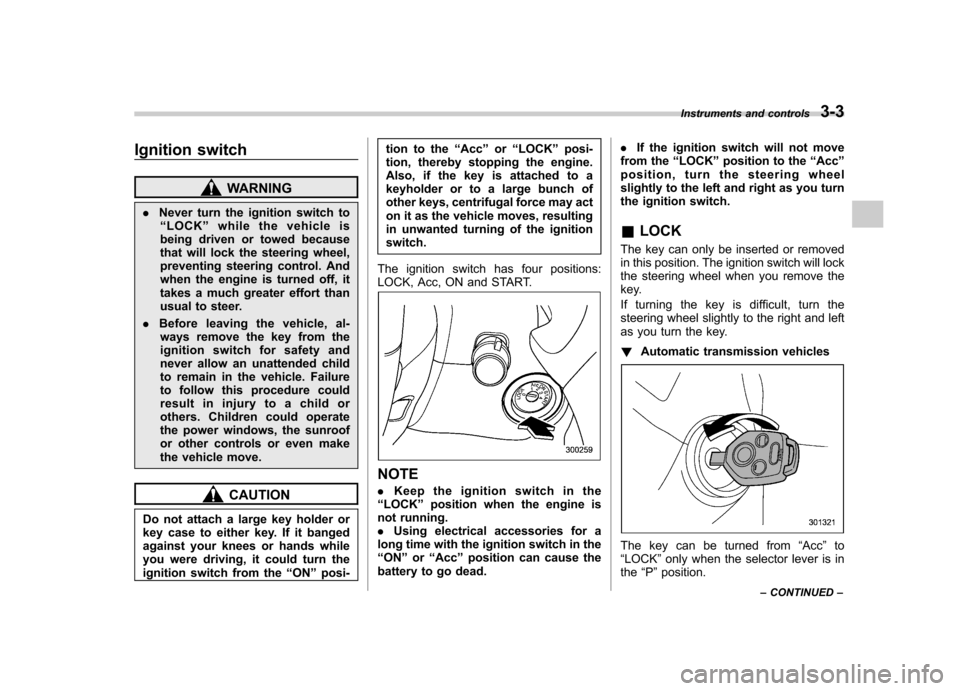
The ignition switch has four positions:
LOCK, Acc, ON and START.
NOTE . Keep the ignition switch in the
“ LOCK ”position when the engine is
not running. . Using electrical accessories for a
long time with the ignition switch in the“ ON ”or “Acc ”position can cause the
battery to go dead. .
If the ignition switch will not move
from the “LOCK ”position to the “Acc ”
position, turn the steering wheel
slightly to the left and right as you turn
the ignition switch. & LOCK
The key can only be inserted or removed
in this position. The ignition switch will lock
the steering wheel when you remove the
key.
If turning the key is difficult, turn the
steering wheel slightly to the right and left
as you turn the key. ! Automatic transmission vehicles
The key can be turned from “Acc ”to
“ LOCK ”only when the selector lever is in
the “P ”position. Instruments and controls
3-3
– CONTINUED –
Page 134 of 447

off. NOTE
If the connection between the combina-
tion meter and battery is broken for any
reason such as vehicle maintenance or
fuse replacement, the data recorded on
the trip meter will be lost. &Current and average fuel consumption
U.S.-spec. models
Canada-spec. models
1) Current fuel consumption
2) Average fuel consumption
Current fuel consumption shows the rate
of fuel consumption at the present mo-
ment. Average fuel consumption shows
the average rate of fuel consumption since
the trip meter was last reset.
When the vehicle speed is less than
approximately 6 mph (9.5 km/h), the
current fuel consumption is not displayed.
The displayed number with “A ” is the
average fuel consumption corresponding
to the A trip meter indication, and the
displayed number with “B ” is the average
fuel consumption corresponding to the B
trip meter indication.
Those A and B indications can be
changed by depressing the trip knob. When either of the trip meter indications is
reset, the corresponding average fuel
consumption value is also reset. NOTE .
The indicated values vary in accor-
dance with changes in the vehicle ’s
running conditions. Also, the indicated
values may differ slightly from the
actual values and should thus be
treated only as a guide.. When either trip meter indication is
reset, the average fuel consumption
corresponding to that trip meter indica-
tion is not shown until the vehicle has
subsequently covered a distance of 1
mile (or 1 km). Instruments and controls
3-11
– CONTINUED –
Page 148 of 447

&Odometer
This meter displays the odometer when
the ignition switch is in the “LOCK ”, “Acc ”
or “ON ”position.
The odometer shows the total distance
that the vehicle has been driven.
If you press the trip knob when the ignition
switch is in the “LOCK ”position, the
odometer/trip meter will light up. If you
do not press the trip knob within 10
seconds of illumination of the odometer/
trip meter, the odometer/trip meter will go
off.
Also, if you open and close the driver ’s
door within 10 seconds of illumination of
the odometer/trip meter, the odometer/trip
meter will go off. &
Double trip meterThis meter displays the two trip meters
when the ignition switch is in the “LOCK ”,
“ Acc ”or “ON ”position.
The trip meter shows the distance that the
vehicle has been driven since you last set
it to zero.
To change the mode indication, briefly
push the knob.
Each press of the knob changes the mode
indication alternately.
To set the trip meter to zero, select the A
trip or B trip meter by pushing the knob
and keep the knob pushed for more than 2seconds.
If you press the trip knob when the ignition
switch is in the “LOCK ”position, the
odometer/trip meter will light up. It is
possible to switch between the A trip
meter and B trip meter indications while
the odometer/trip meter is lit up. If you do
not press the trip knob within 10 seconds
of illumination of the odometer/trip meter,
the odometer/trip meter will go off.
Also, if you open and close the driver ’s
door within 10 seconds of illumination of
the odometer/trip meter, the odometer/trip
meter will go off.
CAUTION
To ensure safety, do not attempt to
change the function of the indicator
during driving, as an accident couldresult.
NOTE
If the connection between the combina-
tion meter and battery is broken for any
reason such as vehicle maintenance or
fuse replacement, the data recorded on
the trip meter will be lost. Instruments and controls
3-25
– CONTINUED –
Page 158 of 447

If any of these conditions occur,
have the ABS system repaired at
the first available opportunity by
your SUBARU dealer.
The ABS warning light illuminates to-
gether with the brake system warning light
if the EBD system becomes faulty. For
further details of the EBD system fault
warning, refer to “Brake system warning
light ”.
NOTE
If the warning light behavior is as
described in the following conditions,
the ABS system may be considerednormal. . The warning light illuminates right
after the engine is started but goes out
immediately, remaining off. . The warning light remains on after
the engine has been started, but it goes
out when the vehicle speed reaches
approximately 8 mph (12 km/h).. The warning light illuminates during
driving, but it goes out immediately and
remains off.
When driving with an insufficient battery
voltage such as when the engine is jump
started, the ABS warning light may illumi-
nate. This is due to the low battery voltage
and does not indicate a malfunction. When the battery becomes fully charged,
the light will go out.
& Brake system
warning light
WARNING
. Driving with the brake system
warning light on is dangerous.
This indicates your brake system
may not be working properly. If
the light remains on, have the
brakes inspected by a SUBARU
dealer immediately.
. If at all in doubt about whether
the brakes are operating prop-
erly, do not drive the vehicle.
Have your vehicle towed to the
nearest SUBARU dealer for re-
pair.
This light has the following three functions: ! Parking brake warning
The light illuminates with the parking
brake applied while the ignition switch is
in the “ON ”position. It goes out when the
parking brake is fully released. ! Brake fluid level warning
This light illuminates when the brake fluid
level has dropped to near the “MIN ”level of the brake fluid reservoir with the ignition
switch in the
“ON ”position and with the
parking brake fully released.
If the brake system warning light should
illuminate while driving (with the parking
brake fully released and with the ignition
switch positioned in “ON ”), it could be an
indication of leaking of brake fluid or worn
brake pads. If this occurs, immediately
stop the vehicle at the nearest safe place
and check the brake fluid level. If the fluid
level is below the “MIN ”mark in the
reservoir, do not drive the vehicle. Have
the vehicle towed to the nearest SUBARU
dealer for repair. ! Electronic Brake Force Distribution
(EBD) system warning
The brake system warning light also
illuminates if a malfunction occurs in the
EBD system. In that event, it illuminates
together with the ABS warning light.
The EBD system may be faulty if the
brake system warning light and ABS
warning light illuminate simultaneously
during driving.
Even if the EBD system fails, the conven-
tional braking system will still function.
However, the rear wheels will be more
prone to locking when the brakes are
applied harder than usual and the vehi-cle ’s motion may therefore become some- Instruments and controls
3-35
– CONTINUED –
Page 169 of 447

3-46Instruments and controls
Light control switch
WARNING
To prevent battery discharge result-
ing from accidentally leaving your
lights on when your vehicle is
parked, the light switch operates
only when the ignition switch is inthe “ON ”position. In any other
position, the vehicle ’s lights will be
out.
If you park your vehicle on a road-
side at night, use the hazard warn-
ing flasher to alert the other drivers.
The light switch operates only when the
ignition switch is in the “ON ”position. &
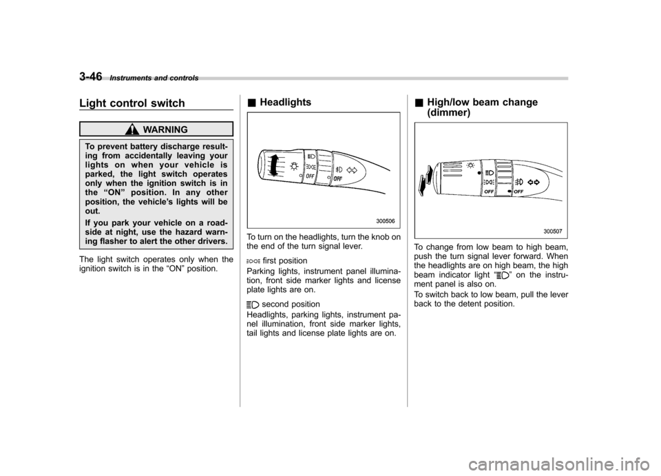
Headlights
To turn on the headlights, turn the knob on
the end of the turn signal lever.
first position
Parking lights, instrument panel illumina-
tion, front side marker lights and license
plate lights are on.
second position
Headlights, parking lights, instrument pa-
nel illumination, front side marker lights,
tail lights and license plate lights are on. &
High/low beam change (dimmer)
To change from low beam to high beam,
push the turn signal lever forward. When
the headlights are on high beam, the high
beam indicator light “
”on the instru-
ment panel is also on.
To switch back to low beam, pull the lever
back to the detent position.