2009 SUBARU FORESTER low beam
[x] Cancel search: low beamPage 18 of 384

&Light control and wiper control levers/switches1) Windshield wiper (page 3-29)
2) Mist (page 3-30)
3) Windshield washer (page 3-30)
4) Rear window wiper and washer switch
(page 3-30)
5) Wiper intermittent time control switch (page 3-29)
6) Wiper control lever (page 3-28)
7) Light control switch (page 3-24)
8) Fog light switch (page 3-27)
9) Headlight ON/OFF (page 3-24)
10) Headlight flasher High/Low beam change (page 3-25)
11) Turn signal (page 3-26) 15
– CONTINUED –
Page 23 of 384

20
&Warning and indicator lights
Mark Name Page
Seatbelt warning light 3-9
Front passenger ’s seat-
belt warning light 3-9
SRS airbag system
warning light3-11
/Front passenger
’s fron-
tal airbag ON indicator 3-11
/Front passenger
’s fron-
tal airbag OFF indicator 3-11
CHECK ENGINE
warning light/Malfunction
indicator lamp3-12
Coolant temperature low
indicator light/Coolant
temperature high warn-
ing light3-13
Charge warning light 3-13
Oil pressure warning light
3-13
AT OIL TEMP warning
light (AT vehicles)
3-14Mark Name Page
/ABS warning light 3-15
/Brake system warning light
3-16
Door open warning light 3-17
All-Wheel Drive warning
light (AT vehicles)
3-17
Hill start assist warning
light (MT vehicles)
3-17
Vehicle Dynamics Con-
trol operation indicator light3-18
Vehicle Dynamics Con-
trol warning light/Vehicle
Dynamics Control OFF
indicator light3-18
Turn signal indicator lights
3-20
High beam indicator light 3-20
Front fog light indicator
light (if equipped)3-21
Security indicator light 3-19 Mark Name Page
Headlight indicator light 3-21
Cruise control indicator light
3-20
Cruise control set indi-
cator light
3-21
Low fuel warning light 3-17
Low tire pressure warn-
ing light (U.S.-spec. models)3-14
SPORT mode indicator
light (AT vehicles)
3-20
Page 112 of 384

Ignition switch..................................................... 3-3
LOCK .................................................................. 3-3
Acc..................................................................... 3-4
ON...................................................................... 3-4
START ................................................................ 3-4
Key reminder chime ............................................ 3-5
Ignition switch light ............................................. 3-5
Hazard warning flasher ....................................... 3-5
Meters and gauges. ............................................. 3-5
Combination meter illumination ........................... 3-5
Canceling the function for meter/gauge needle movement upon turning on the ignition switch ............................................................... 3-6
Speedometer ....................................................... 3-6
Odometer/Trip meter ............................................ 3-6
Tachometer ......................................................... 3-7
Fuel gauge .......................................................... 3-8
Warning and indicator lights .............................. 3-9
Seatbelt warning light and chime ......................... 3-9
SRS airbag system warning light ........................ 3-11
Front passenger ’s frontal airbag ON and OFF
indicators ......................................................... 3-11
CHECK ENGINE warning light/Malfunction indicator lamp .................................................. 3-12
Coolant temperature low indicator light/Coolant temperature high warning light ......................... 3-13
Charge warning light .......................................... 3-13
Oil pressure warning light .................................. 3-13
AT OIL TEMP warning light (AT vehicles).. ........... 3-14
Low tire pressure warning light (U.S.-spec. models) .......................................... 3-14 ABS warning light
.............................................. 3-15
Brake system warning light ................................ 3-16
Low fuel warning light ....................................... 3-17
Hill start assist warning light (MT vehicles) .... ..... 3-17
Door open warning light .................................... 3-17
All-Wheel Drive warning light (AT vehicles) .... ..... 3-17
Vehicle Dynamics Control operation indicator light ................................................................ 3-18
Vehicle Dynamics Control warning light/Vehicle Dynamics Control OFF indicator light ............... 3-18
Security indicator light ....................................... 3-19
SPORT mode indicator light (AT vehicles) ..... ..... 3-20
Selector lever and gear position indicator (AT vehicles) .................................................... 3-20
Turn signal indicator lights ................................. 3-20
High beam indicator light ................................... 3-20
Cruise control indicator light .............................. 3-20
Cruise control set indicator light ........................ 3-21
Front fog light indicator light (if equipped) ..... ..... 3-21
Headlight indicator light ..................................... 3-21
Clock .................................................................. 3-21
Information display ............................................ 3-22
Outside temperature indicator .. .......................... 3-22
Average fuel consumption ................................. 3-23
Light control switch ........................................... 3-24
Headlights ......................................................... 3-24
High/low beam change (dimmer) ........................ 3-25
Headlight flasher ............................................... 3-25
Daytime running light system ... .......................... 3-25
Automatic headlight beam leveler (vehicles with HID headlights) ................................................ 3-26
Instruments and controls
3
Page 131 of 384

3-20Instruments and controls
NOTE
Even if the security indicator light
flashes irregularly or its fuse blows
(the light does not flash if its fuse is
blown), the immobilizer system will
function normally. & SPORT mode indicator
light (AT vehicles)
This light illuminates when the ignition
switch is turned to the “ON ”position and
turns off after the engine has started.
When the selector lever is moved to the
manual gate, the SPORT mode is se-
lected and the indicator light illuminates.
Refer to the “SPORT mode ”section in
chapter 7. &
Selector lever and gear posi-
tion indicator (AT vehicles)
This indicator shows the position of the
selector lever.
When the manual mode is selected, the
gear position indicator (which shows the
current gear selection) and the upshift/
downshift indicator light up. Refer to the“Automatic transmission ”section in chap-
ter 7. & Turn signal indicator lights
These lights show the operation of the turn
signal or lane change signal.
If the indicator lights do not blink or blink
rapidly, the turn signal bulb may be burned
out. Replace the bulb as soon as possible. Refer to the
“Replacing bulbs ”section in
chapter 11.
& High beam indicator light
This light shows that the headlights are in
the high beam mode.
This indicator light also illuminates when
the headlight flasher is operated. &Cruise control indica-
tor light
The cruise control indicator light illumi-
nates when the ignition switch is turned tothe “ON ”position and turns off after
approximately 3 seconds.
This light illuminates when the “CRUISE ”
main switch is pressed.
If you press the main switch button while
turning the ignition switch “ON ”, the cruise
control function is deactivated and the“ CRUISE ”indicator light flashes. To re-
activate the cruise control function, turn
the ignition switch back to the “Acc ”or
“ LOCK ”position, and then turn it again to
the “ON ”position.
Page 136 of 384

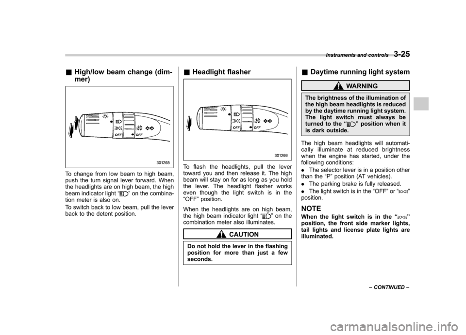
&High/low beam change (dim- mer)
To change from low beam to high beam,
push the turn signal lever forward. When
the headlights are on high beam, the high
beam indicator light “
”on the combina-
tion meter is also on.
To switch back to low beam, pull the lever
back to the detent position. &
Headlight flasher
To flash the headlights, pull the lever
toward you and then release it. The high
beam will stay on for as long as you hold
the lever. The headlight flasher works
even though the light switch is in the“OFF ”position.
When the headlights are on high beam,
the high beam indicator light “
”on the
combination meter also illuminates.
CAUTION
Do not hold the lever in the flashing
position for more than just a fewseconds. &
Daytime running light system
WARNING
The brightness of the illumination of
the high beam headlights is reduced
by the daytime running light system.
The light switch must always be
turned to the “
”position when it
is dark outside.
The high beam headlights will automati-
cally illuminate at reduced brightness
when the engine has started, under the
following conditions: . The selector lever is in a position other
than the “P ”position (AT vehicles).
. The parking brake is fully released.
. The light switch is in the “OFF ”or “
”
position.
NOTE
When the light switch is in the “
”
position, the front side marker lights,
tail lights and license plate lights areilluminated. Instruments and controls
3-25
– CONTINUED –
Page 138 of 384

at all.Front fog light switch (if equipped)
The front fog lights operate only when the
low beam headlights are illuminated.
However, the front fog lights turn off when
the headlights are switched to high beam.
To turn on the front fog lights, turn the front
fog light switch on the turn signal lever
upward to the“
”position. To turn off the
front fog lights, turn the switch back down
to the “OFF ”position.
The indicator light located on the combi-
nation meter will illuminate when the front
fog lights are on. Instruments and controls
3-27
Page 261 of 384

8-14Driving tips
roof rail must be used together
with the roof rack and any appro-
priate carrying attachment that
may be needed. The roof rail
must never be used alone to
carry cargo. Otherwise, damage
to the roof or paint or a danger-
ous road hazard due to loss of
cargo could result.
NOTE
Remember that the vehicle ’s center of
gravity is altered with the weight of the
load on the roof, thus affecting drivingcharacteristics.
Drive carefully. Avoid rapid starts, hard
cornering and abrupt stops. Crosswind
effects will be increased. Trailer hitch (dealer option)
WARNING
. Never exceed the maximum
weight specified for the trailer
hitch. Exceeding the maximum
weight could cause an accident
resulting in serious personal in-
juries. Permissible trailer weight
changes depending on the situa-
tion. Refer to the next section“ Trailer towing ”for possible re-
commendations and limitations.
. Trailer brakes are required when
the towing load exceeds 1,000
lbs (453 kg). Be sure your trailer
has safety chains and that each
chain will hold the trailer ’s max-
imum gross weight. Towing trai-
lers without safety chains could
create a traffic safety hazard if
the trailer separates from the
hitch due to coupling damage or
hitch ball damage.
. Be sure to check the hitch pin
and safety pin for positive lock-
ing placement before towing a
trailer. If the ball mount comes off
the hitch receiver, the trailer
could get loose and create a traffic safety hazard.
. Use only the ball mount supplied
with this hitch. Use the hitch only
as a weight carrying hitch. Do not
use with any type of weight
distributing hitch.
. The standard bumper beam must
be installed after you remove the
trailer hitch. Consult a SUBARU
dealer for purchase of a standard
bumper beam if you do not have
the original.
. Safety performance is decreased
and there is increased risk of
injury to passengers in the case
of an accident if the trailer hitch
or a standard bumper beam is
not installed. One of them must
always be installed on the vehi-cle.
. If a trailer hitch is installed, it is
not possible to install the rear
towing hook.
When you tow a trailer, follow the instruc-
tions in the next section “Trailer towing ”.
& Connecting a trailer
1. Remove the receiver cover from the
hitch receiver tube. Then insert the ball
mount into the hitch receiver tube.
Page 284 of 384

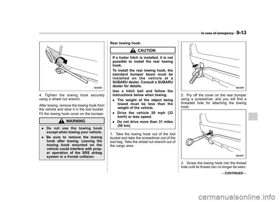
4. Tighten the towing hook securely
using a wheel nut wrench.
After towing, remove the towing hook from
the vehicle and stow it in the tool bucket.
Fit the towing hook cover on the bumper.
WARNING
. Do not use the towing hook
except when towing your vehicle.
. Be sure to remove the towing
hook after towing. Leaving the
towing hook mounted on the
vehicle could interfere with prop-
er operation of the SRS airbag
system in a frontal collision. Rear towing hook:
CAUTION
If a trailer hitch is installed, it is not
possible to install the rear towinghook.
To install the rear towing hook, the
standard bumper beam must be
installed on the vehicle at a
SUBARU dealer. Consult a SUBARU
dealer for details.
Use a hitch ball and follow the
instructions below when towing. . The weight of the object being
towed must be less than the
weight of the vehicle.
. Drive the vehicle 20 mph (32
km/h) or less speed.
. Do not drive more than 31 miles
(50 km).
1. Take the towing hook out of the tool
bucket and take the screwdriver out of the
tool bag. Take the wheel nut wrench out of
the cargo area.
2. Pry off the cover on the rear bumper
using a screwdriver, and you will find a
threaded hole for attaching the towinghook.
3. Screw the towing hook into the thread
hole until its thread can no longer be seen. In case of emergency
9-13
– CONTINUED –