2009 SUBARU FORESTER four wheel drive
[x] Cancel search: four wheel drivePage 114 of 384

Ignition switch
WARNING
. Never turn the ignition switch to
“ LOCK ”while the vehicle is
being driven or towed because
that will lock the steering wheel,
preventing steering control. And
when the engine is turned off, it
takes a much greater effort than
usual to steer.
. Before leaving the vehicle, al-
ways remove the key from the
ignition switch for safety and
never allow an unattended child
to remain in the vehicle. Failure
to follow this procedure could
result in injury to a child or
others. Children could operate
the power windows, the moon-
roof or other controls or even
make the vehicle move.
CAUTION
Do not attach a large key holder or
key case to either key. If it banged
against your knees or hands while
you are driving, it could turn the
ignition switch from the “ON ”posi- tion to the
“Acc ”or “LOCK ”posi-
tion, thereby stopping the engine.
Also, if the key is attached to a
keyholder or to a large bunch of
other keys, centrifugal force may act
on it as the vehicle moves, resulting
in unwanted turning of the ignitionswitch.
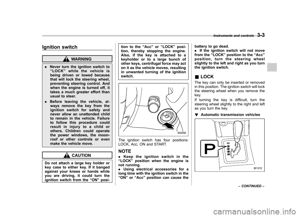
The ignition switch has four positions:
LOCK, Acc, ON and START. NOTE . Keep the ignition switch in the
“ LOCK ”position when the engine is
not running. . Using electrical accessories for a
long time with the ignition switch in the“ ON ”or “Acc ”position can cause the battery to go dead..
If the ignition switch will not move
from the “LOCK ”position to the “Acc ”
position, turn the steering wheel
slightly to the left and right as you turn
the ignition switch. & LOCK
The key can only be inserted or removed
in this position. The ignition switch will lock
the steering wheel when you remove the
key.
If turning the key is difficult, turn the
steering wheel slightly to the right and left
as you turn the key. ! Automatic transmission vehicles
Instruments and controls 3-3
– CONTINUED –
Page 126 of 384

vehicle to ensure that the replacement or
alternate tires and wheels allow the TPMS
to continue to function properly.
Should the warning light illuminate stea-
dily after blinking for approximately one
minute, have the system inspected by
your nearest SUBARU dealer as soon aspossible.
WARNING
If this light does not illuminate
briefly after the ignition switch is
turned ON or the light illuminates
steadily after blinking for approxi-
mately one minute, you should have
your Tire Pressure Monitoring Sys-
tem checked at a SUBARU dealer as
soon as possible.
If this light illuminates while driving,
never brake suddenly and keep
driving straight ahead while gradu-
ally reducing speed. Then slowly
pull off the road to a safe place.
Otherwise an accident involving
serious vehicle damage and serious
personal injury could occur.
If this light still illuminates while
driving after adjusting the tire pres-
sure, a tire may have significant
damage and a fast leak that causes
the tire to lose air rapidly. If you have a flat tire, replace it with a spare tire
as soon as possible.
When a spare tire is mounted or a
wheel rim is replaced without the
original pressure sensor/transmitter
being transferred, the Low tire pres-
sure warning light will illuminates
steadily after blinking for approxi-
mately one minute. This indicates
the TPMS is unable to monitor all
four road wheels. Contact your
SUBARU dealer as soon as possible
for tire and sensor replacement and/
or system resetting. If the light
illuminates steadily after blinking
for approximately one minute,
promptly contact a SUBARU dealer
to have the system inspected.
CAUTION
The tire pressure monitoring system
is NOT a substitute for manually
checking tire pressure. The tire
pressure should be checked peri-
odically (at least monthly) using a
tire gauge. After any change to tire
pressure(s), the tire pressure mon-
itoring system will not re-check tire
inflation pressures until the vehicle
is first driven more than 20 mph (32
km/h). After adjusting the tire pres- sures, increase the vehicle speed to
at least 20 mph (32 km/h) to start the
TPMS re-checking of the tire infla-
tion pressures. If the tire pressures
are now above the severe low
pressure threshold, the low tire
pressure warning light should turn
off a few minutes later. Therefore, be
sure to install the specified size for
the front and rear tires.
& ABS warning light
The ABS warning light illuminates when
the ignition switch is turned to the “ON ”
position and turns off after approximately 2seconds.
This is an indication that the ABS system
is working properly.
CAUTION
If the warning light behaves as
follows, the ABS system may not
work properly.
When the warning light is on, the
ABS function shuts down; however,
the conventional brake system con-
tinues to operate normally. . The warning light does not illu-
minate when the ignition switch
is turned to the “ON ”position.
Instruments and controls
3-15
– CONTINUED –
Page 215 of 384

7-6Starting and operating
State emission testing (U.S. only)
At state inspection time, remember to
tell your inspection or service station in
advance not to place your SUBARU
AWD vehicle on a two-wheel dynam-
ometer. Otherwise, serious transmis-
sion damage will result.
Some states have started using dynam-
ometers in their state inspection programs
in order to meet their obligation under
federal law to implement stricter vehicle
emission standards to reduce air pollution
from vehicles. A dynamometer is a tread-
mill or roller-like testing device that allows
your vehicle ’s wheels to turn while the
vehicle remains in one place. Depending
on the severity of a state ’s air pollution
problems, the states must adopt either a“ basic ”or “enhanced ”vehicle emission
inspection test. Normally, a portion of the
basic emission test consists of an emis-
sion inspector inserting an analyzer probe
into the exhaust pipe of an idling vehicle
for a short period of time. States with more
severe air pollution problems are required
to adopt an enhanced vehicle emission
test. This test simulates actual driving
conditions on a dynamometer and permits
more accurate measurement of tailpipe
emitted pollution than the basic emission test.
The U.S. Environmental Protection
Agency (EPA) and states using two-wheel
dynamometers in their emission testing
programs have
EXEMPTEDSUBARU
AWD vehicles from the portion of the
testing program that involves a two-wheel
dynamometer.
There are some states that use four-wheel
dynamometers in their testing programs.
When properly used, that equipment will
not damage an AWD SUBARU vehicle.
Under no circumstances should the rear
wheels be jacked off the ground, nor
should the driveshaft be disconnected for
state emission testing.
WARNING
Testing of an All-Wheel Drive vehicle
must NEVER be performed on a
single two-wheel dynamometer. At-
tempting to do so will result in
uncontrolled vehicle movement and
may cause an accident or injuries to
persons nearby.
CAUTION
Resultant vehicle damage due to
improper testing is not covered
under the SUBARU Limited War-
ranty and is the responsibility of
the state inspection program or its
contractors or licensees.
The EPA has issued regulations for
inspecting the On-Board Diagnostic
(OBD) system as part of the state emis-
sions inspection. The OBD system is
designed to detect engine and transmis-
sion problems that might cause vehicle
emissions to exceed allowable limits.
These inspections apply to all 1996 model
year and newer passenger cars and light
trucks. Over 30 states plus the District of
Columbia have implemented the OBD
system inspection. . The inspection of the OBD system
consists of a visual operational check of the “CHECK ENGINE ”warning light/mal-
function indicator lamp (MIL) and an
examination of the OBD system with an
electronic scan tool while the engine isrunning. . Avehicle
passes the OBD system
inspection if proper illumination of the “ CHECK ENGINE ”warning light/MIL is
observed, there are nostored diagnostic
Page 225 of 384

7-16Starting and operating
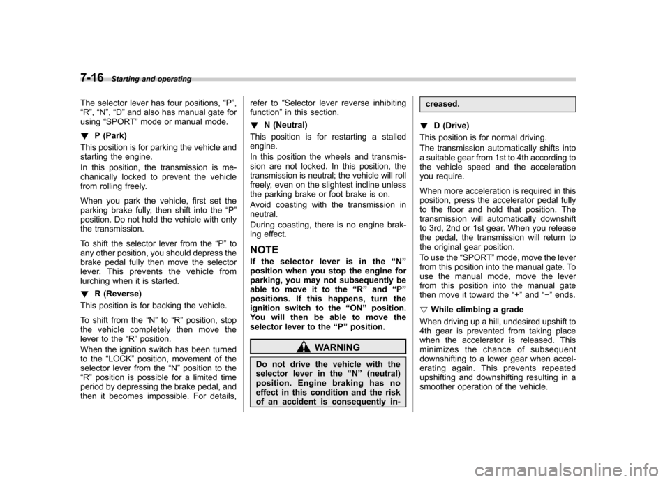
The selector lever has four positions, “P ”,
“ R ”, “N ”, “D ”and also has manual gate for
using “SPORT ”mode or manual mode.
! P (Park)
This position is for parking the vehicle and
starting the engine.
In this position, the transmission is me-
chanically locked to prevent the vehicle
from rolling freely.
When you park the vehicle, first set the
parking brake fully, then shift into the “P ”
position. Do not hold the vehicle with only
the transmission.
To shift the selector lever from the “P ” to
any other position, you should depress the
brake pedal fully then move the selector
lever. This prevents the vehicle from
lurching when it is started. ! R (Reverse)
This position is for backing the vehicle.
To shift from the “N ”to “R ”position, stop
the vehicle completely then move the
lever to the “R ”position.
When the ignition switch has been turned
to the “LOCK ”position, movement of the
selector lever from the “N ”position to the
“ R ” position is possible for a limited time
period by depressing the brake pedal, and
then it becomes impossible. For details, refer to
“Selector lever reverse inhibiting
function ”in this section.
! N (Neutral)
This position is for restarting a stalledengine.
In this position the wheels and transmis-
sion are not locked. In this position, the
transmission is neutral; the vehicle will roll
freely, even on the slightest incline unless
the parking brake or foot brake is on.
Avoid coasting with the transmission in neutral.
During coasting, there is no engine brak-
ing effect.
NOTE
If the selector lever is in the “N ”
position when you stop the engine for
parking, you may not subsequently be
able to move it to the “R ” and “P ”
positions. If this happens, turn the
ignition switch to the “ON ”position.
You will then be able to move the
selector lever to the “P ” position.
WARNING
Do not drive the vehicle with the
selector lever in the “N ” (neutral)
position. Engine braking has no
effect in this condition and the risk
of an accident is consequently in- creased.
! D (Drive)
This position is for normal driving.
The transmission automatically shifts into
a suitable gear from 1st to 4th according to
the vehicle speed and the acceleration
you require.
When more acceleration is required in this
position, press the accelerator pedal fully
to the floor and hold that position. The
transmission will automatically downshift
to 3rd, 2nd or 1st gear. When you release
the pedal, the transmission will return to
the original gear position.
To use the “SPORT ”mode, move the lever
from this position into the manual gate. To
use the manual mode, move the lever
from this position into the manual gate
then move it toward the “+ ” and “� ” ends.
! While climbing a grade
When driving up a hill, undesired upshift to
4th gear is prevented from taking place
when the accelerator is released. This
minimizes the chance of subsequent
downshifting to a lower gear when accel-
erating again. This prevents repeated
upshifting and downshifting resulting in a
smoother operation of the vehicle.
Page 235 of 384

7-26Starting and operating
Vehicle Dynamics Control system
WARNING
Always use the utmost care in driving –overconfidence because
you are driving with a Vehicle Dy-
namics Control system equipped
vehicle could easily lead to a ser-
ious accident.
CAUTION
. Even if your vehicle is equipped
with Vehicle Dynamics Control,
winter tires or snow chains
should be used when driving on
snow-covered or icy roads; in
addition, vehicle speed should
be reduced considerably. Simply
having a Vehicle Dynamics Con-
trol system does not guarantee
that the vehicle will be able to
avoid accidents in any situation.
. Activation of the Vehicle Dy-
namics Control system is an
indication that the road being
travelled on has a slippery sur-
face; since having Vehicle Dy-
namics Control is no guarantee that full vehicle control will be
maintained at all times and under
all conditions, its activation
should be seen as a sign that
the speed of the vehicle should
be reduced considerably.
. Whenever suspension compo-
nents, steering components, or
an axle are removed from a
vehicle equipped with Vehicle
Dynamics Control, have an
authorized SUBARU dealer per-
form an inspection of that sys-tem.
. The following precautions should
be observed in order to ensure
that the Vehicle Dynamics Con-
trol system is operating properly: – All four wheels should be
fitted with tires of the same
size, type, and brand. Further-
more, the amount of wear
should be the same for all
four tires.
– Keep the tire pressure at the
proper level as shown on the
vehicle placard attached to
the driver ’s side door pillar.
– Use only the specified tem-
porary spare tire to replace a
flat tire. With a temporary spare tire, the effectiveness of
the Vehicle Dynamics Control
system is reduced and this
should be taken into account
when driving the vehicle in
such a condition.
In the event of wheelspin and/or skidding
on a slippery road surface and/or during
cornering and/or an evasive maneuver,
the Vehicle Dynamics Control system
adjusts the engine ’s output and the
wheels ’respective braking forces to help
maintain traction and directional control. . Traction Control Function
The traction control function is designed to
prevent spinning of the driving wheels on
slippery road surfaces, thereby helping to
maintain traction and directional control.
Activation of this function is shown by
steady illumination of the Vehicle Dy-
namics Control operation indicator light. . Skid Suppression Function
The skid suppression function is designed
to help maintain directional stability by
suppressing the wheels ’tendency to slide
sideways during steering operations. Acti-
vation of this function is shown by flashing
of the Vehicle Dynamics Control operation
indicator light.
Page 236 of 384

NOTE .Slight twitching of the brake pedal
may be felt when the Vehicle Dynamics
Control system operates; a small de-
gree of vehicle or steering wheel shak-
ing may also be noticed in this situa-
tion. These are normal characteristics
of Vehicle Dynamics Control operation
and are no cause for alarm.. When driving off immediately after
starting the engine, a short-lived opera-
tion noise may be noticed coming from
the engine compartment. This noise is
generated as a result of a check being
performed on the Vehicle Dynamics
Control system and is normal.. Depending on the timing of activa-
tion of the brakes, the brake pedal may
seem to jolt when you drive off after
starting the engine. This is a conse-
quence of the Vehicle Dynamics Con-
trol operational check and is normal.. In the circumstances listed in the
following, the vehicle may be more
unstable than it feels to the driver.
The Vehicle Dynamics Control System
may therefore operate. Such operation
does not indicate a system fault.
–on gravel-covered or rutted
roads – on unfinished roads
– when the vehicle is fitted with snow tires or winter tires
. Activation of the Vehicle Dynamics
Control system will cause operation of
the steering wheel to feel slightly
different compared to that for normalconditions. . Even if the vehicle is equipped with
a Vehicle Dynamics Control system, it
is important that winter tires be used
when driving on snow-covered or icy
roads. (All four wheels should be fitted
with tires of the same size and brand.)
Furthermore, if snow chains are to be
used, they should be fitted on the front
wheels. When a vehicle is fitted with
snow chains, however, the effective-
ness of the Vehicle Dynamics Control
system is reduced and this should be
taken into account when driving the
vehicle in such a condition. . It is always important to reduce
speed when appro aching a corner,
even if the vehicle is equipped with
Vehicle Dynamics Control. . All four wheels should be fitted with
tires of the same size, type, and brand;
furthermore, the amount of wear
should be the same for all four tires. If
these precautions are not observed
and non-matching tires are used, it is
quite possible that the Vehicle Dy-
namics Control system will be unable to operate correctly as intended. .
Always turn off the engine before
replacing a tire as failure to do so may
render the Vehicle Dynamics Control
system unable to operate correctly. & Vehicle Dynamics Control
system monitor
! Vehicle Dynamics Control opera-
tion indicator light
The indicator light illuminates when the
ignition switch is turned to the ON position;
it turns off approximately 2 seconds later.
This indicator light flashes during activa-
tion of the skid suppression function and is
illuminated steadily during activation of the
traction control function.
The following two situations could indicate Starting and operating
7-27
– CONTINUED –
Page 239 of 384

7-30Starting and operating
gine. .Whentheswitchispressedto
deactivate the Vehicle Dynamics Con-
trol system, the vehicle ’s running per-
formance is comparable with that of a
vehicle that does not have a Vehicle
Dynamics Control system. Do not de-
activate the Vehicle Dynamics Control
system except when absolutely neces-
sary. Tire pressure monitoring
system (TPMS) (U.S.-spec.models)
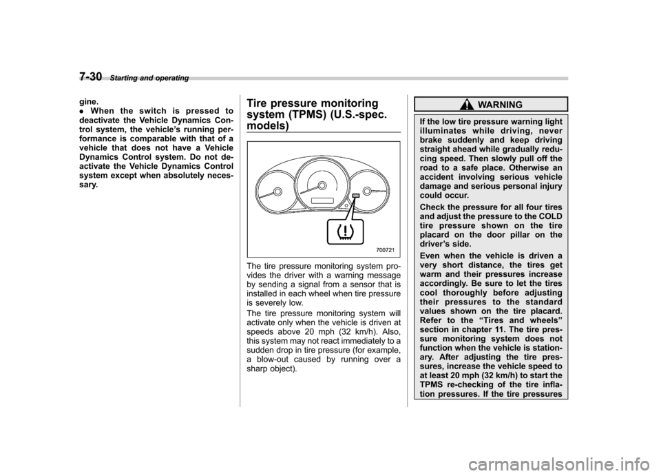
The tire pressure monitoring system pro-
vides the driver with a warning message
by sending a signal from a sensor that is
installed in each wheel when tire pressure
is severely low.
The tire pressure monitoring system will
activate only when the vehicle is driven at
speeds above 20 mph (32 km/h). Also,
this system may not react immediately to a
sudden drop in tire pressure (for example,
a blow-out caused by running over a
sharp object).
WARNING
If the low tire pressure warning light
illuminates while driving, never
brake suddenly and keep driving
straight ahead while gradually redu-
cing speed. Then slowly pull off the
road to a safe place. Otherwise an
accident involving serious vehicle
damage and serious personal injury
could occur.
Check the pressure for all four tires
and adjust the pressure to the COLD
tire pressure shown on the tire
placard on the door pillar on thedriver ’s side.
Even when the vehicle is driven a
very short distance, the tires get
warm and their pressures increase
accordingly. Be sure to let the tires
cool thoroughly before adjusting
their pressures to the standard
values shown on the tire placard.
Refer to the “Tires and wheels ”
section in chapter 11. The tire pres-
sure monitoring system does not
function when the vehicle is station-
ary. After adjusting the tire pres-
sures, increase the vehicle speed to
at least 20 mph (32 km/h) to start the
TPMS re-checking of the tire infla-
tion pressures. If the tire pressures
Page 240 of 384

are now above the severe low
pressure threshold, the low tire
pressure warning light should turn
off a few minutes later.
If this light still illuminates while
driving after adjusting the tire pres-
sure, a tire may have significant
damage and a fast leak that causes
the tire to lose air rapidly. If you have
a flat tire, replace it with a spare tire
as soon as possible.
When a spare tire is mounted or a
wheel rim is replaced without the
original pressure sensor/transmitter
being transferred, the low tire pres-
sure warning light will illuminate
steadily after blinking for approxi-
mately 1 minute. This indicates the
TPMS is unable to monitor all four
road wheels. Contact your SUBARU
dealer as soon as possible for tire
and sensor replacement and/or sys-
tem resetting.
Do not inject any tire liquid or
aerosol tire sealant into the tires,
as this may cause a malfunction of
the tire pressure sensors. If the light
illuminates steadily after blinking for
approximately 1 minute, promptly
contact a SUBARU dealer to have
the system inspected.CAUTION
Do not place metal film or any metal
parts in the cargo room/trunk. This
may cause poor reception of the
signals from the tire pressure sen-
sors, and the tire pressure monitor-
ing system will not function prop-
erly.
NOTE
This device complies with Part 15 of
the FCC Rules and with RSS-210 of
Industry Canada. Operation is subject
to the following two conditions: (1) This
device may not cause harmful inter-
ference, and (2) this device must
accept any interference received, in-
cluding interference that may cause
undesired operation.
Changes or modifications not ex-
pressly approved by the party respon-
sible for compliance could void theuser ’s authority to operate the equip-
ment. Parking your vehicle &
Parking brake
To set the parking brake, press the brake
pedal firmly and hold it down until the
parking brake lever is fully pulled up.
To release the parking brake, pull the lever
up slightly, press the release button, then
lower the lever while keeping the button pressed.
When the parking brake is set while the
engine is running, the parking brake
warning light illuminates. After starting
the vehicle, be sure that the warning light
has gone out before the vehicle is driven.
Refer to the “Warning and indicator lights ”
section in chapter 3. Starting and operating
7-31
– CONTINUED –