2009 SUBARU FORESTER air condition
[x] Cancel search: air conditionPage 311 of 384
11-16Maintenance and service
& Replacing the air cleaner element
Replace the air cleaner element according
to the maintenance schedule in the“ Warranty and Maintenance Booklet ”. Un-
der extremely dusty conditions, replace it
more frequently. It is recommended that
you always use genuine SUBARU parts. ! Non-turbo models
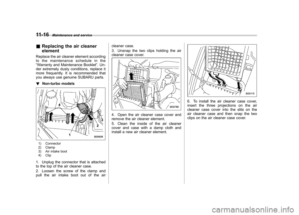
1) Connector
2) Clamp
3) Air intake boot
4) Clip
1. Unplug the connector that is attached
to the top of the air cleaner case.
2. Loosen the screw of the clamp and
pull the air intake boot out of the air cleaner case.
3. Unsnap the two clips holding the air
cleaner case cover.
4. Open the air cleaner case cover and
remove the air cleaner element.
5. Clean the inside of the air cleaner
cover and case with a damp cloth and
install a new air cleaner element.
6. To install the air cleaner case cover,
insert the three projections on the air
cleaner case cover into the slits on the
air cleaner case and then snap the two
clips on the air cleaner case cover.
Page 313 of 384
11-18Maintenance and service
Spark plugs
It may be difficult to replace the spark
plugs. It is recommended that you have
the spark plugs replaced by your
SUBARU dealer.
The spark plugs should be replaced
according to the maintenance schedule
in the“Warranty and Maintenance Book-
let ”.
CAUTION
. When disconnecting the spark
plug cables, always grasp the
spark plug cap, not the cables.
. Make sure the cables are re-
placed in the correct order. &
Recommended spark plugs
Non-turbo models: FR5AP-11 (NGK)
Turbo models:
SILFR6A (NGK) Drive belts
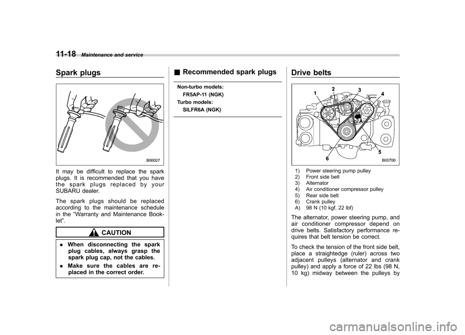
1) Power steering pump pulley
2) Front side belt
3) Alternator
4) Air conditioner compressor pulley
5) Rear side belt
6) Crank pulley
A) 98 N (10 kgf, 22 lbf)
The alternator, power steering pump, and
air conditioner compressor depend on
drive belts. Satisfactory performance re-
quires that belt tension be correct.
To check the tension of the front side belt,
place a straightedge (ruler) across two
adjacent pulleys (alternator and crank
pulley) and apply a force of 22 lbs (98 N,
10 kg) midway between the pulleys by
Page 325 of 384
11-30Maintenance and service
result in the need for costly brake
rotor repair or replacement.
& Breaking-in of new brake
pads and linings
When replacing the brake pad or lining,
use only genuine SUBARU parts. After
replacement, the new parts must be
broken in as follows: ! Brake pad and lining
While maintaining a speed of 30 to 40
mph (50 to 65 km/h), step on the brake
pedal lightly. Repeat this five or moretimes. ! Parking brake lining
1.Drivethevehicleataspeedof
approximately 22 mph (35 km/h).
2. With the parking brake release button
pushed in, pull the parking brake lever
SLOWLY and GENTLY. (Pulling with a
force of approximately 33 lbs [147 N, 15kg].)
3. Drive the vehicle for approximately
220 yards (200 meters) in this condition.
4. Wait 5 to 10 minutes for the parking
brake to cool down. Repeat this proce-dure.
5. Check the parking brake stroke. If the
parking brake stroke is out of the specified range, adjust it by turning the adjusting nut
located on the parking brake lever.
Parking brake stroke: 7–8 notches / 44 lbs (196 N, 20 kg)
WARNING
A safe location and situation should
be selected for break-in driving.
CAUTION
Pulling the parking brake lever too
forcefully may cause the rear
wheels to lock. To avoid this, be
certain to pull the lever up slowly
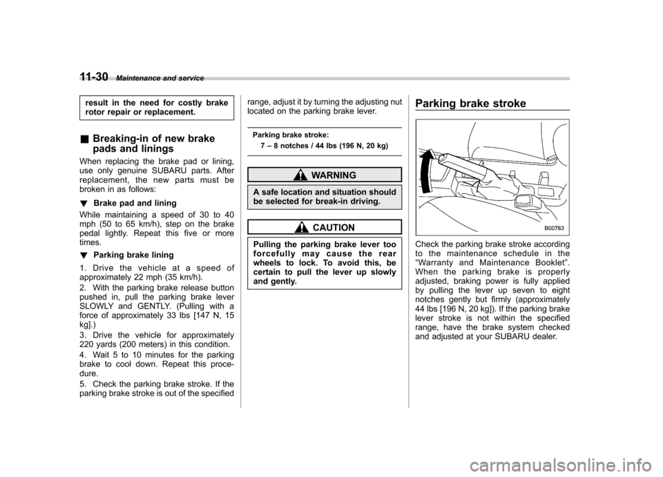
and gently. Parking brake stroke
Check the parking brake stroke according
to the maintenance schedule in the“
Warranty and Maintenance Booklet ”.
When the parking brake is properly
adjusted, braking power is fully applied
by pulling the lever up seven to eight
notches gently but firmly (approximately
44 lbs [196 N, 20 kg]). If the parking brake
lever stroke is not within the specified
range, have the brake system checked
and adjusted at your SUBARU dealer.
Page 326 of 384
Tires and wheels &Types of tires
You should be familiar with type of tires
present on your vehicle.
The factory-fitted tires are all-season tires. ! All season tires
All season tires are designed to provide
an adequate measure of traction, handling
and braking performance in year-round
driving including snowy and icy road
conditions. However all season tires do
not offer as much traction performance as
winter (snow) tires in heavy or loose snow
or on icy roads.
All season tires are identified by “ALL
SEASON ”and/or “M+S ”(Mud & Snow) on
the tire sidewall. ! Summer tires
Summer tires are high-speed capability
tires best suited for highway driving under
dry conditions.
Summer tires are inadequate for driving
on slippery roads such as on snow-
covered or icy roads.
If you drive your vehicle on snow-covered
or icy roads, we strongly recommend the
use of winter (snow) tires.
When installing winter tires, be sure to
replace all four tires. !
Winter (snow) tires
Winter tires are best suited for driving on
snow-covered and icy roads. However
winter tires do not perform as well as
summer tires and all season tires on roads
other than snow-covered and icy roads.
& Tire pressure monitoring
system (TPMS) (U.S.-spec.models)
The tire pressure monitoring system pro-
vides the driver with a warning message
by sending a signal from a sensor that is
installed in each wheel when tire pressure
is severely low. The tire pressure monitor-
ing system will activate only when the
vehicle is driven. Also, this system may
not react immediately to a sudden drop in
tire pressure (for example, a blow-out
caused by running over a sharp object).
If you adjust the tire pressures in a warm
garage and will then drive the vehicle in
cold outside air, the resulting drop in tire
pressures may cause the low tire pressure
warning light to illuminate. To avoid this
problem when adjusting the tire pressures
in a warm garage, inflate the tires to
pressures higher than those shown on the
tire placard. Specifically, inflate them by an
extra 1 psi (6.9 kPa, 0.07 kgf/cm
2) for
every difference of 10 8F (5.6 8C) between the temperature in the garage and the
temperature outside. By way of example,
the following table shows the required tire
pressures that correspond to various out-
side temperatures when the temperature
in the garage is 60
8F (15.6 8C).
Example:
Tire size: P215/65R16 96H
Standard tire pressures:
Front: 30 psi (210 kPa, 2.1 kgf/cm
2)
Rear: 29 psi (200 kPa, 2.0 kgf/cm2)
Garage temperature: 60 8F (15.6 8C)
Outside
temperature Adjusted pressure
[psi (kPa, kgf/cm
2)]
front rear
30 8F( �18C) 33
(230, 2.3) 32
(220, 2.2)
10 8F( �12 8C) 35
(240, 2.4) 34
(235, 2.35)
� 10 8F( �23 8C) 37
(255, 2.55) 36
(250, 2.5)
Example:
Tire size: P225/55R17 95H
Standard tire pressures:
Front: 32 psi (220 kPa, 2.2 kgf/cm
2)
Rear: 30 psi (210 kPa, 2.1 kgf/cm2)
Garage temperature: 60 8F (15.6 8C)
Maintenance and service
11-31
– CONTINUED –
Page 330 of 384
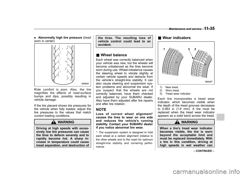
.Abnormally high tire pressure (tread
worn in center)
Ride comfort is poor. Also, the tire
magnifies the effects of road-surface
bumps and dips, possibly resulting in
vehicle damage.
If the tire placard shows tire pressures for
the vehicle when fully loaded, adjust the
tire pressures to the values that match
current loading conditions.
WARNING
Driving at high speeds with exces-
sively low tire pressures can cause
the tires to deform severely and to
rapidly become hot. A sharp in-
crease in temperature could cause
tread separation, and destruction of the tires. The resulting loss of
vehicle control could lead to anaccident.
& Wheel balance
Each wheel was correctly balanced when
your vehicle was new, but the wheels will
become unbalanced as the tires become
worn during use. Wheel imbalance causes
the steering wheel to vibrate slightly at
certain vehicle speeds and detracts from
the vehicle ’s straight-line stability. It can
also cause steering and suspension sys-
tem problems and abnormal tire wear. If
you suspect that the wheels are not
correctly balanced, have them checked
and adjusted by your SUBARU dealer.
Also have them adjusted after tire repairs
and after tire rotation. NOTE
Loss of correct wheel alignment*
causes the tires to wear on one side
and reduces the vehicle ’s running
stability. Contact your SUBARU dealer
if you notice abnormal tire wear.
*: The suspension system is designed to hold
each wheel at a certain alignment (relative to
the other wheels and to the road) for optimum
straight-line stability and cornering perfor- mance. &
Wear indicators
1) New tread
2) Worn tread
3) Tread wear indicator
Each tire incorporates a tread wear
indicator, which becomes visible when
the depth of the tread grooves decreases
to 0.063 in (1.6 mm). A tire must be
replaced when the tread wear indicator
appears as a solid band across the tread.
WARNING
When a tire ’s tread wear indicator
becomes visible, the tire is worn
beyond the acceptable limit and
must be replaced immediately. With
a tire in this condition, driving at
high speeds in wet weather can Maintenance and service
11-35
– CONTINUED –
Page 354 of 384

Fuse
panel Fuse
rating Circuit
16 10A .Illumination
17 15A .Seat heaters
18 10A .Back-up light
19 Empty
20 10A .Accessory power outlet
(instrument panel)
21 7.5A .Starter relay
22 15A .Air conditioner
. Rear window defogger
relay coil
23 15A .Rear wiper
. Rear window washer
24 15A .Audio unit
. Clock
25 15A .SRS airbag system
26 7.5A .Power window relay
. Radiator main fan relay
. Tail and illumination re-
lay
27 15A .Blower fan
28 15A .Blower fan
29 15A .Fog light
30 30A .Front wiper
31 7.5A .Auto air conditioner unit
. Integrated unit Fuse
panel Fuse
rating Circuit
32 Empty
33 7.5A .ABS/Vehicle dynamics
control unit Specifications
12-7
– CONTINUED –
Page 360 of 384
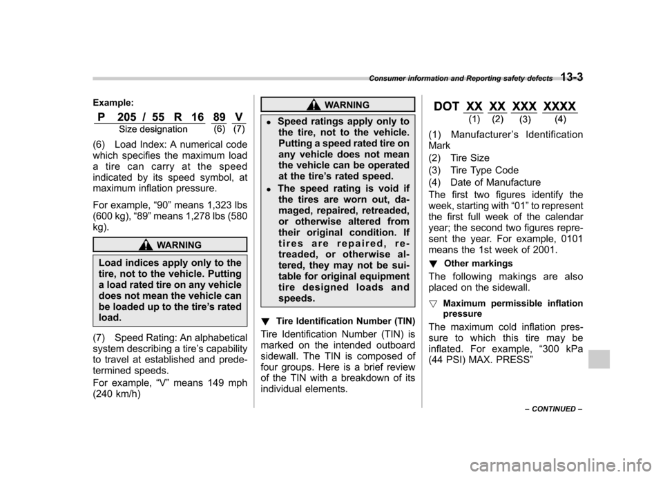
Example:
(6) Load Index: A numerical code
which specifies the maximum load
a tire can carry at the speed
indicated by its speed symbol, at
maximum inflation pressure.
For example,“90 ”means 1,323 lbs
(600 kg), “89 ”means 1,278 lbs (580
kg).
WARNING
Load indices apply only to the
tire, not to the vehicle. Putting
a load rated tire on any vehicle
does not mean the vehicle can
be loaded up to the tire ’s rated
load.
(7) Speed Rating: An alphabetical
system describing a tire ’s capability
to travel at established and prede-
termined speeds.
For example, “V ” means 149 mph
(240 km/h)
WARNING
. Speed ratings apply only to
the tire, not to the vehicle.
Putting a speed rated tire on
any vehicle does not mean
the vehicle can be operated
at the tire ’s rated speed.
. The speed rating is void if
the tires are worn out, da-
maged, repaired, retreaded,
or otherwise altered from
their original condition. If
tires are repaired, re-
treaded, or otherwise al-
tered, they may not be sui-
table for original equipment
tire designed loads andspeeds.
! Tire Identification Number (TIN)
Tire Identification Number (TIN) is
marked on the intended outboard
sidewall. The TIN is composed of
four groups. Here is a brief review
of the TIN with a breakdown of its
individual elements.
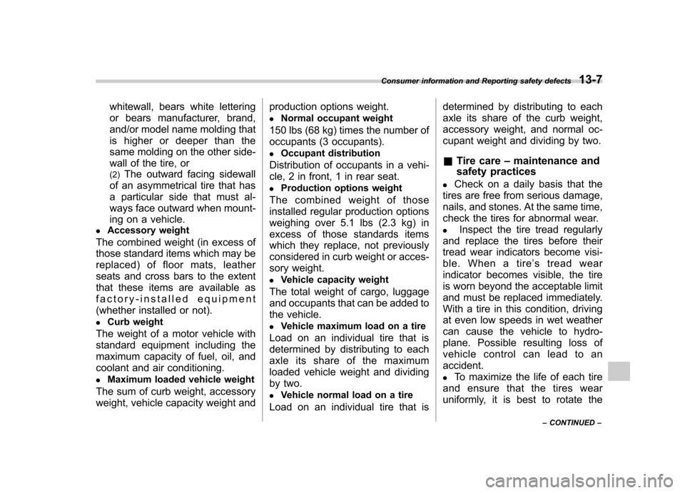
(1) Manufacturer ’s Identification
Mark
(2) Tire Size
(3) Tire Type Code
(4) Date of Manufacture
The first two figures identify the
week, starting with “01 ”to represent
the first full week of the calendar
year; the second two figures repre-
sent the year. For example, 0101
means the 1st week of 2001.
! Other markings
The following makings are also
placed on the sidewall. ! Maximum permissible inflation
pressure
The maximum cold inflation pres-
sure to which this tire may be
inflated. For example, “300 kPa
(44 PSI) MAX. PRESS ”
Consumer information and Reporting safety defects
13-3
– CONTINUED –
Page 364 of 384
whitewall, bears white lettering
or bears manufacturer, brand,
and/or model name molding that
is higher or deeper than the
same molding on the other side-
wall of the tire, or (2)The outward facing sidewall
of an asymmetrical tire that has
a particular side that must al-
ways face outward when mount-
ing on a vehicle.
. Accessory weight
The combined weight (in excess of
those standard items which may be
replaced) of floor mats, leather
seats and cross bars to the extent
that these items are available as
factory-installed equipment
(whether installed or not). . Curb weight
The weight of a motor vehicle with
standard equipment including the
maximum capacity of fuel, oil, and
coolant and air conditioning. . Maximum loaded vehicle weight
The sum of curb weight, accessory
weight, vehicle capacity weight and production options weight.
. Normal occupant weight
150 lbs (68 kg) times the number of
occupants (3 occupants). . Occupant distribution
Distribution of occupants in a vehi-
cle, 2 in front, 1 in rear seat.. Production options weight
The combined weight of those
installed regular production options
weighing over 5.1 lbs (2.3 kg) in
excess of those standards items
which they replace, not previously
considered in curb weight or acces-
sory weight. . Vehicle capacity weight
The total weight of cargo, luggage
and occupants that can be added to
the vehicle. . Vehicle maximum load on a tire
Load on an individual tire that is
determined by distributing to each
axle its share of the maximum
loaded vehicle weight and dividing
by two. . Vehicle normal load on a tire
Load on an individual tire that is determined by distributing to each
axle its share of the curb weight,
accessory weight, and normal oc-
cupant weight and dividing by two. &
Tire care –maintenance and
safety practices
. Check on a daily basis that the
tires are free from serious damage,
nails, and stones. At the same time,
check the tires for abnormal wear.. Inspect the tire tread regularly
and replace the tires before their
tread wear indicators become visi-
ble. When a tire ’s tread wear
indicator becomes visible, the tire
is worn beyond the acceptable limit
and must be replaced immediately.
With a tire in this condition, driving
at even low speeds in wet weather
can cause the vehicle to hydro-
plane. Possible resulting loss of
vehicle control can lead to anaccident. . To maximize the life of each tire
and ensure that the tires wear
uniformly, it is best to rotate the
Consumer information and Reporting safety defects
13-7
– CONTINUED –