2009 SUBARU FORESTER fuel pressure
[x] Cancel search: fuel pressurePage 23 of 384

20
&Warning and indicator lights
Mark Name Page
Seatbelt warning light 3-9
Front passenger ’s seat-
belt warning light 3-9
SRS airbag system
warning light3-11
/Front passenger
’s fron-
tal airbag ON indicator 3-11
/Front passenger
’s fron-
tal airbag OFF indicator 3-11
CHECK ENGINE
warning light/Malfunction
indicator lamp3-12
Coolant temperature low
indicator light/Coolant
temperature high warn-
ing light3-13
Charge warning light 3-13
Oil pressure warning light
3-13
AT OIL TEMP warning
light (AT vehicles)
3-14Mark Name Page
/ABS warning light 3-15
/Brake system warning light
3-16
Door open warning light 3-17
All-Wheel Drive warning
light (AT vehicles)
3-17
Hill start assist warning
light (MT vehicles)
3-17
Vehicle Dynamics Con-
trol operation indicator light3-18
Vehicle Dynamics Con-
trol warning light/Vehicle
Dynamics Control OFF
indicator light3-18
Turn signal indicator lights
3-20
High beam indicator light 3-20
Front fog light indicator
light (if equipped)3-21
Security indicator light 3-19 Mark Name Page
Headlight indicator light 3-21
Cruise control indicator light
3-20
Cruise control set indi-
cator light
3-21
Low fuel warning light 3-17
Low tire pressure warn-
ing light (U.S.-spec. models)3-14
SPORT mode indicator
light (AT vehicles)
3-20
Page 112 of 384

Ignition switch..................................................... 3-3
LOCK .................................................................. 3-3
Acc..................................................................... 3-4
ON...................................................................... 3-4
START ................................................................ 3-4
Key reminder chime ............................................ 3-5
Ignition switch light ............................................. 3-5
Hazard warning flasher ....................................... 3-5
Meters and gauges. ............................................. 3-5
Combination meter illumination ........................... 3-5
Canceling the function for meter/gauge needle movement upon turning on the ignition switch ............................................................... 3-6
Speedometer ....................................................... 3-6
Odometer/Trip meter ............................................ 3-6
Tachometer ......................................................... 3-7
Fuel gauge .......................................................... 3-8
Warning and indicator lights .............................. 3-9
Seatbelt warning light and chime ......................... 3-9
SRS airbag system warning light ........................ 3-11
Front passenger ’s frontal airbag ON and OFF
indicators ......................................................... 3-11
CHECK ENGINE warning light/Malfunction indicator lamp .................................................. 3-12
Coolant temperature low indicator light/Coolant temperature high warning light ......................... 3-13
Charge warning light .......................................... 3-13
Oil pressure warning light .................................. 3-13
AT OIL TEMP warning light (AT vehicles).. ........... 3-14
Low tire pressure warning light (U.S.-spec. models) .......................................... 3-14 ABS warning light
.............................................. 3-15
Brake system warning light ................................ 3-16
Low fuel warning light ....................................... 3-17
Hill start assist warning light (MT vehicles) .... ..... 3-17
Door open warning light .................................... 3-17
All-Wheel Drive warning light (AT vehicles) .... ..... 3-17
Vehicle Dynamics Control operation indicator light ................................................................ 3-18
Vehicle Dynamics Control warning light/Vehicle Dynamics Control OFF indicator light ............... 3-18
Security indicator light ....................................... 3-19
SPORT mode indicator light (AT vehicles) ..... ..... 3-20
Selector lever and gear position indicator (AT vehicles) .................................................... 3-20
Turn signal indicator lights ................................. 3-20
High beam indicator light ................................... 3-20
Cruise control indicator light .............................. 3-20
Cruise control set indicator light ........................ 3-21
Front fog light indicator light (if equipped) ..... ..... 3-21
Headlight indicator light ..................................... 3-21
Clock .................................................................. 3-21
Information display ............................................ 3-22
Outside temperature indicator .. .......................... 3-22
Average fuel consumption ................................. 3-23
Light control switch ........................................... 3-24
Headlights ......................................................... 3-24
High/low beam change (dimmer) ........................ 3-25
Headlight flasher ............................................... 3-25
Daytime running light system ... .......................... 3-25
Automatic headlight beam leveler (vehicles with HID headlights) ................................................ 3-26
Instruments and controls
3
Page 120 of 384

Warning and indicator lights
Several of the warning and indicator lights
illuminate momentarily and then turn off
when the ignition switch is initially turned
to the“ON ”position. This permits check-
ing the operation of the bulbs.
Apply the parking brake and turn the
ignition switch to the “ON ”position. The
following lights illuminate:
: Seatbelt warning light
(The seatbelt warning light turns off only
when the driver fastens the seatbelt.)
: Front passenger ’s seatbelt warning
light
(The seatbelt warning light turns off only
when the front seat passenger fastens theseatbelt.)
: SRS airbag system warning light
ON /
: Front passenger ’s frontal airbag
ON indicator light
/: Front passenger ’s frontal airbag
OFF indicator light
: CHECK ENGINE warning light/Mal-
function indicator lamp
: Coolant temperature high warning light
: Charge warning light
: Oil pressure warning light
: AT OIL TEMP warning light(AT vehicles)
: Low tire pressure warning light(U.S.- spec. models)
/: ABS warning light
/: Brake system warning light
: Low fuel warning light
: Hill start assist warning light (MT vehicles)
: Door open warning light
: All-Wheel Drive warning light (AT vehicles)
: Vehicle Dynamics Control operation indicator light
: Vehicle Dynamics Control warning light/Vehicle Dynamics Control OFF
indicator light
: SPORT mode indicator light(AT vehicles)
: Cruise control indicator light
: Cruise control set indicator light
If any lights fail to illuminate, it indicates a
burned-out bulb or a malfunction of the corresponding system.
Consult your authorized SUBARU dealer
for repair. &
Seatbelt warning light
and chime
Your vehicle is equipped with a seatbelt
warning device at the driver ’s and front
passenger ’s seat, as required by current
safety standards.
With the ignition switch turned to the “ON ”
position, this device reminds the driver
and front passenger to fasten their seat-
belts by illuminating the warning lights in
the locations indicated in the following
illustration and sounding a chime.
Driver ’s warning light Instruments and controls
3-9
– CONTINUED –
Page 125 of 384

3-14Instruments and controls
CAUTION
Do not operate the engine with the
oil pressure warning light on. This
may cause serious engine damage.
& AT OIL TEMP warning
light (AT vehicles)
The AT oil temperature warning light “AT
OIL TEMP ”illuminates when the ignition
switch is turned to the “ON ”position and
turns off after the engine has started.
If this light illuminates when the engine is
running, it may indicate that the automatic
transmission fluid temperature is too hot.
If the light illuminates while driving, im-
mediately stop the vehicle in a safe place
and let the engine idle until the warning
light turns off. ! Automatic transmission control
system warning
If the light flashes after the engine starts, it
may indicate that the automatic transmis-
sion control system is not working prop-
erly. Contact your nearest SUBARU deal-
er for service immediately. &
Low tire pressure
warning light (U.S.-spec.models)
When the ignition switch is turned to the “ON ”position, the low tire pressure warn-
ing light will illuminate for approximately 2
seconds to check that the tire pressure
monitoring system (TPMS) is functioning
properly. If there is no problem and all tires
are properly inflated, the light will turn off.
Each tire, including the spare (if provided),
should be checked monthly when cold
and inflated to the inflation pressure
recommended by the vehicle manufac-
turer on the vehicle placard or tire inflation
pressure label. (If your vehicle has tires of
a different size than the size indicated on
the vehicle placard or tire inflation pres-
sure label, you should determine the
proper inflation pressure for those tires.)
As an added safety feature, your vehicle
has been equipped with a tire pressure
monitoring system (TPMS) that illuminates
a low tire pressure telltale when one or
more of your tires is significantly under-
inflated. Accordingly, when the low tire
pressure telltale illuminates, you should
stop and check your tires as soon as
possible, and inflate them to the proper
pressure. Driving on a significantly under-
inflated tire causes the tire to overheat and can lead to tire failure. Under-inflation also
reduces fuel efficiency and tire tread life,
and may affect the vehicle
’s handling and
stopping ability.
Please note that the TPMS is not a
substitute for proper tire maintenance,
and it is the driver ’s responsibility to
maintain correct tire pressure, even if
under-inflation has not reached the level
to trigger illumination of the TPMS low tire
pressure telltale.
Your vehicle has also been equipped with
a TPMS malfunction indicator to indicate
when the system is not operating properly.
The TPMS malfunction indicator is com-
bined with the low tire pressure telltale.
When the system detects a malfunction,
the telltale will flash for approximately one
minute and then remain continuously
illuminated. This sequence will continue
upon subsequent vehicle start-ups as long
as the malfunction exists. When the
malfunction indicator is illuminated, the
system may not be able to detect or signal
low tire pressure as intended. TPMS
malfunctions may occur for a variety of
reasons, including the installation of re-
placement or alternate tires or wheels on
the vehicle that prevent the TPMS from
functioning properly. Always check the
TPMS malfunction telltale after replacing
one or more tires or wheels on your
Page 210 of 384

Fuel...................................................................... 7-2
Fuel requirements ............................................... 7-2
Fuel filler lid and cap ........................................... 7-3
State emission testing (U.S. only) ...................... 7-6
Preparing to drive ............................................... 7-7
Starting the engine .............................................. 7-7
Manual transmission vehicle ................................ 7-7
Automatic transmission vehicle ........................... 7-8
Stopping the engine ............................................ 7-9
Remote engine start system (dealer option) ..... 7-9
Starting your vehicle .......................................... 7-10
Remote start safety features ............................... 7-10
Entering the vehicle while it is running via remote start ................................................................. 7-10
Entering the vehicle following remote engine start shutdown ......................................................... 7-10
Pre-heating or pre-cooling the interior of the vehicle ............................................................. 7-11
Service mode ..................................................... 7-11
Remote transmitter programming and programmable feature option ............................ 7-11
System maintenance .......................................... 7-12
Manual transmission .......................................... 7-13
Shifting speeds .................................................. 7-14
Driving tips ........................................................ 7-14
Automatic transmission ..................................... 7-15
Selector lever ..................................................... 7-15
Selector lever reverse inhibiting function . ........... 7-17
Selection of manual mode .................................. 7-18
Maximum speeds ............................................... 7-19
Driving tips ........................................................ 7-19 SPORT mode
..................................................... 7-20
Shift lock release ............................................... 7-20
Power steering ................................................... 7-21
Braking ............................................................... 7-21
Braking tips ....................................................... 7-21
Brake system .................................................... 7-22
Disc brake pad wear warning indicators ............. 7-22
ABS (Anti-lock Brake System) .......................... 7-23
ABS system self-check ...................................... 7-23
ABS warning light .............................................. 7-23
Electronic Brake Force Distribution (EBD) system ............................................................. 7-24
Steps to take if EBD system fails ....................... 7-25
Vehicle Dynamics Control system .................... 7-26
Vehicle Dynamics Control system monitor..... ..... 7-27
Vehicle Dynamics Control OFF switch ................ 7-29
Tire pressure monitoring system (TPMS) (U.S.-spec. models). ........................................ 7-30
Parking your vehicle ......................................... 7-31
Parking brake .................................................... 7-31
Parking tips ....................................................... 7-32
Hill start assist system (MT vehicles) .............. 7-33
Hill start assist warning light .............................. 7-34
Cruise control .................................................... 7-34
To set cruise control .......................................... 7-35
To temporarily cancel the cruise control ............. 7-35
To turn off the cruise control .............................. 7-36
To change the cruising speed .. .......................... 7-36
Cruise control indicator light .............................. 7-37
Cruise control set indicator light ........................ 7-38
Starting and operating
7
Page 249 of 384

8-2Driving tips
New vehicle break-in driving –the first 1,000 miles (1,600
km)
The performance and long life of your
vehicle are dependent on how you handle
and care for your vehicle while it is new.
Follow these instructions during the first
1,000 miles (1,600 km): . Do not race the engine. And do not
allow engine speed to exceed 4,000 rpm
except in an emergency. . Do not drive at one constant engine or
vehicle speed for a long time, either fast or
slow. . Avoid starting suddenly and rapid
acceleration, except in an emergency.. Avoid hard braking, except in an
emergency.
The same break-in procedures should be
applied to an overhauled engine, newly
mounted engine or when brake pads or
brake linings are replaced with new ones. Fuel economy hints
The following suggestions will help to save fuel. .
Select the proper gear position for the
speed and road conditions.. Avoid sudden acceleration or decelera-
tion. Always accelerate gently until you
reach the desired speed. Then try to
maintain that speed for as long aspossible. . Do not pump the accelerator and avoid
racing the engine.. Avoid unnecessary engine idling.
. Keep the engine properly tuned.
. Keep the tires inflated to the correct
pressure shown on the tire placard, which
is located under the door latch on thedriver ’s side. Low pressure will increase
tire wear and fuel consumption. . Use the air conditioner only when
necessary.. Keep the front and rear wheels in
proper alignment.. Avoid carrying unnecessary luggage or
cargo. Engine exhaust gas (carbon
monoxide)
WARNING
. Never inhale engine exhaust gas.
Engine exhaust gas contains
carbon monoxide, a colorless
and odorless gas which is dan-
gerous, or even lethal, if inhaled.
. Always properly maintain the en-
gine exhaust system to prevent
engine exhaust gas from enter-
ing the vehicle.
. Never run the engine in a closed
space, such as a garage, except
for the brief time needed to drive
the vehicle in or out of it.
. Avoid remaining in a parked
vehicle for a lengthy time while
the engine is running. If that is
unavoidable, then use the venti-
lation fan to force fresh air into
the vehicle.
. Always keep the front ventilator
inlet grille free from snow, leaves
or other obstructions to ensure
that the ventilation system al-
ways works properly.
. If at any time you suspect that
Page 298 of 384

Maintenance schedule
The scheduled maintenance items re-
quired to be serviced at regular intervals
are shown in the“Warranty and Main-
tenance Booklet ”.
For details of your maintenance schedule,
read the separate “Warranty and Main-
tenance Booklet ”. Maintenance precautions
When maintenance and service are re-
quired, it is recommended that all work be
done by an authorized SUBARU dealer.
If you perform maintenance and service
by yourself, you should familiarize yourself
with the information provided in this
section on general maintenance and
service for your SUBARU.
Incorrect or incomplete service could
cause improper or unsafe vehicle opera-
tion. Any problems caused by improper
maintenance and service performed by
you are not eligible for warranty coverage.
WARNING
. Testing of an All-Wheel Drive
vehicle must NEVER be per-
formed on a single two-wheel
dynamometer or similar appara-
tus. Attempting to do so will
result in transmission damage
and in uncontrolled vehicle
movement and may cause an
accident or injuries to persons
nearby.
. Always select a safe area when
performing maintenance on yourvehicle. .
Always be very careful to avoid
injury when working on the vehi-
cle. Remember that some of the
materials in the vehicle may be
hazardous if improperly used or
handled, for example, batteryacid.
. Your vehicle should only be ser-
viced by persons fully competent
to do so. Serious personal injury
may result to persons not experi-
enced in servicing vehicles.
. Always use the proper tools and
make certain that they are wellmaintained.
. Never get under the vehicle sup-
ported only by a jack. Always use
safety stands to support thevehicle.
. Never keep the engine running in
a poorly ventilated area, such as
a garage or other closed areas.
. Do not smoke or allow open
flames around the fuel or battery.
This will cause a fire.
. Because the fuel system is under
pressure, replacement of the fuel
filter should be performed only
by your SUBARU dealer.
. Wear adequate eye protection to Maintenance and service
11-3
– CONTINUED –
Page 308 of 384

&Engine coolant
! Checking the coolant level
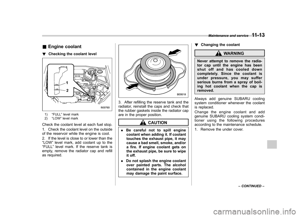
1) “FULL ”level mark
2) “LOW ”level mark
Check the coolant level at each fuel stop.
1. Check the coolant level on the outside
of the reservoir while the engine is cool.
2. If the level is close to or lower than the “ LOW ”level mark, add coolant up to the
“ FULL ”level mark. If the reserve tank is
empty, remove the radiator cap and refill
as required.
3. After refilling the reserve tank and the
radiator, reinstall the caps and check that
the rubber gaskets inside the radiator cap
are in the proper position.
CAUTION
. Be careful not to spill engine
coolant when adding it. If coolant
touches the exhaust pipe, it may
cause a bad smell, smoke, and/or
a fire. If engine coolant gets on
the exhaust pipe, be sure to wipe
it off.
. Do not splash the engine coolant
over painted parts. The alcohol
contained in the engine coolant
may damage the paint surface. !
Changing the coolant
WARNING
Never attempt to remove the radia-
tor cap until the engine has been
shut off and has cooled down
completely. Since the coolant is
under pressure, you may suffer
serious burns from a spray of boil-
ing hot coolant when the cap isremoved.
Always add genuine SUBARU cooling
system conditioner whenever the coolant
is replaced.
Change the engine coolant and add
genuine SUBARU cooling system condi-
tioner using the following procedures
according to the maintenance schedule.
1. Remove the under cover. Maintenance and service
11-13
– CONTINUED –