2009 SUBARU FORESTER change time
[x] Cancel search: change timePage 101 of 384

2-14Keys and doors
Alarm system
The alarm system helps to protect your
vehicle and valuables from theft. The horn
sounds, the turn signal lights flash, and
the dome light and the map light illuminate
(only when the dome light switch is in the“DOOR ”position) if someone attempts to
break into your vehicle. The starter motor
is also interrupted to prevent starting the
vehicle without a key.
The system can be armed and disarmed
with the remote transmitter.
The system does not operate when the
key is inserted into the ignition switch.
Your vehicle ’s alarm system has been set
for activation at the time of shipment from
the factory. You can set the system for
deactivation yourself or have it done by
your SUBARU dealer. & System operation
The alarm system will give the following
alarms when triggered: . The vehicle ’s horn will sound, the turn
signal lights will flash for 30 seconds and
the dome light illuminates (only when the
dome light switch is in the “DOOR ”
position). . If any door or the rear gate remains open after the 30-second period, the horn
will continue to sound for a maximum of 3
minutes. If the door or the rear gate is
closed while the horn is sounding, the
horn will stop sounding with a delay of up
to 30 seconds.
The alarm is triggered by: .
Opening a door, the rear gate
. Physical impact to the vehicle, such as
forced entry (only vehicles with shock
sensors (dealer option))
NOTE
The alarm system can be set to trigger
illumination of the dome light. The
dome light notification is deactivated
as the factory setting. A SUBARU
dealer can activate the system. Contact
your SUBARU dealer for details. & Activating and deactivating
the alarm system
To change the setting of your vehicle ’s
alarm system for activation or deactiva-
tion, do the following.
1. Disarm the alarm system (refer to “ Disarming the system ”in this section).
2. Sit in the driver ’s seat and shut all
doors and the rear gate.
3. Turn the ignition switch to the “ON ” position.
4. Hold down the UNLOCK side of the driver
’s power door locking switch, open
the driver ’s door within the following 1
second, and wait 10 seconds without
releasing the switch. The setting will then
be changed as follows:
If the system was previously activated:
The odometer/trip meter screen displays “ AL oF ”and the horn sounds twice,
indicating that the system is now deacti-vated.
If the system was previously deacti- vated:
The odometer/trip meter screen displays “ AL on ”and the horn sounds once,
indicating that the system is now acti-vated.
NOTE
You may have the above setting
change done by your SUBARU dealer. & If you have accidentally trig-
gered the alarm system
! To stop the alarm
Do any of the following operations: . Press any button on the remote trans-
mitter.. Turn the ignition switch to the “ON ”
Page 103 of 384

2-16Keys and doors
flashing rapidly. After rapid flashing for 30
seconds (standby time), the indicator
lights will then flash slowly (twice approxi-
mately every 2 seconds), indicating that
the system has been armed for surveil-lance. NOTE . The system can be armed even if the
engine hood, the windows and/or
moonroof (if equipped) are open. Al-
ways make sure that they are fully
closed before arming the system.. The 30-second standby time can be
eliminated if you prefer. Have it per-
formed by your SUBARU dealer.. The system is in the standby mode
for a 30-second period after locking the
doors with the remote transmitter. The
security indicator light will flash at
short intervals during this period.. If any of the following actions are
done during the standby period, the
system will not switch to the surveil-
lance state.
–Doors are unlocked using the
remote transmitter. – Any door (including the rear
gate) is opened.– Ignition switch is turned to the
“ ON ”position. &
Disarming the system
Briefly press the “
”button (for less than
2 seconds) on the remote transmitter. The driver ’s door will unlock, an electronic
chirp will sound twice, the turn signal
lights will flash twice. The flashing of the
security indicator light will then change
slowly (once approximately every 3 sec-
onds from twice approximately every 2
seconds), indicating that the alarm system
has been disarmed. NOTE
After disarming the alarm system,
briefly press the “
”button a second
time within 5 seconds to unlock all
other doors and the rear gate. ! Emergency disarming
If you cannot disarm the system using the
transmitter (i.e. the transmitter is lost,
broken or the transmitter battery is too
weak), you can disarm the system without
using the transmitter.
The system can be disarmed as follows. . Turn the ignition switch from the
“ LOCK ”to the “ON ”position with a
registered key.
& Valet mode
When you choose the valet mode, the
alarm system does not operate. In valet mode, the remote transmitter is used only
for locking and unlocking the doors and
rear gate and panic activation.
To enter the valet mode, change the
setting of your vehicle
’s alarm system for
deactivation mode. Refer to “Activating
and deactivating the alarm system ”in this
section. The security indicator light will
continue to flash once every 3 seconds
indicating that the system is in the valetmode.
To exit valet mode, change the setting of
your vehicle ’s alarm system for activation
mode. Refer to “Activating and deactivat-
ing the alarm system ”in this section.
& Passive arming
When passive arming mode has been
programmed by the dealer, arming of the
system is automatically accomplished
without using the remote transmitter. Note
that in this mode, DOORS MUST BE
MANUALLY LOCKED. ! To enter the passive mode
If you wish to program the passive arming
mode, have it done by your SUBARU
dealer.
Page 112 of 384

Ignition switch..................................................... 3-3
LOCK .................................................................. 3-3
Acc..................................................................... 3-4
ON...................................................................... 3-4
START ................................................................ 3-4
Key reminder chime ............................................ 3-5
Ignition switch light ............................................. 3-5
Hazard warning flasher ....................................... 3-5
Meters and gauges. ............................................. 3-5
Combination meter illumination ........................... 3-5
Canceling the function for meter/gauge needle movement upon turning on the ignition switch ............................................................... 3-6
Speedometer ....................................................... 3-6
Odometer/Trip meter ............................................ 3-6
Tachometer ......................................................... 3-7
Fuel gauge .......................................................... 3-8
Warning and indicator lights .............................. 3-9
Seatbelt warning light and chime ......................... 3-9
SRS airbag system warning light ........................ 3-11
Front passenger ’s frontal airbag ON and OFF
indicators ......................................................... 3-11
CHECK ENGINE warning light/Malfunction indicator lamp .................................................. 3-12
Coolant temperature low indicator light/Coolant temperature high warning light ......................... 3-13
Charge warning light .......................................... 3-13
Oil pressure warning light .................................. 3-13
AT OIL TEMP warning light (AT vehicles).. ........... 3-14
Low tire pressure warning light (U.S.-spec. models) .......................................... 3-14 ABS warning light
.............................................. 3-15
Brake system warning light ................................ 3-16
Low fuel warning light ....................................... 3-17
Hill start assist warning light (MT vehicles) .... ..... 3-17
Door open warning light .................................... 3-17
All-Wheel Drive warning light (AT vehicles) .... ..... 3-17
Vehicle Dynamics Control operation indicator light ................................................................ 3-18
Vehicle Dynamics Control warning light/Vehicle Dynamics Control OFF indicator light ............... 3-18
Security indicator light ....................................... 3-19
SPORT mode indicator light (AT vehicles) ..... ..... 3-20
Selector lever and gear position indicator (AT vehicles) .................................................... 3-20
Turn signal indicator lights ................................. 3-20
High beam indicator light ................................... 3-20
Cruise control indicator light .............................. 3-20
Cruise control set indicator light ........................ 3-21
Front fog light indicator light (if equipped) ..... ..... 3-21
Headlight indicator light ..................................... 3-21
Clock .................................................................. 3-21
Information display ............................................ 3-22
Outside temperature indicator .. .......................... 3-22
Average fuel consumption ................................. 3-23
Light control switch ........................................... 3-24
Headlights ......................................................... 3-24
High/low beam change (dimmer) ........................ 3-25
Headlight flasher ............................................... 3-25
Daytime running light system ... .......................... 3-25
Automatic headlight beam leveler (vehicles with HID headlights) ................................................ 3-26
Instruments and controls
3
Page 117 of 384

3-6Instruments and controls
& Canceling the function for
meter/gauge needle move-
ment upon turning on the
ignition switch
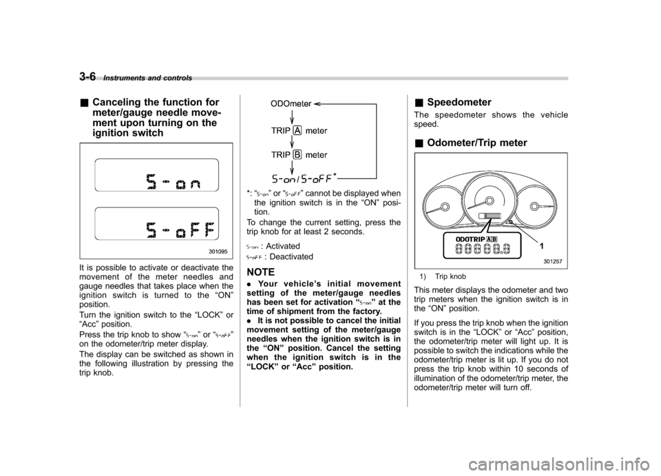
It is possible to activate or deactivate the
movement of the meter needles and
gauge needles that takes place when the
ignition switch is turned to the “ON ”
position.
Turn the ignition switch to the “LOCK ”or
“ Acc ”position.
Press the trip knob to show “
”or “”
on the odometer/trip meter display.
The display can be switched as shown in
the following illustration by pressing the
trip knob.
*: “”or “”cannot be displayed when
the ignition switch is in the “ON ”posi-
tion.
To change the current setting, press the
trip knob for at least 2 seconds.
: Activated
: Deactivated
NOTE . Your vehicle ’s initial movement
setting of the meter/gauge needles
has been set for activation “
”at the
time of shipment from the factory. . It is not possible to cancel the initial
movement setting of the meter/gauge
needles when the ignition switch is inthe “ON ”position. Cancel the setting
whentheignitionswitchisinthe“ LOCK ”or “Acc ”position. &
Speedometer
The speedometer shows the vehiclespeed. & Odometer/Trip meter
1) Trip knob
This meter displays the odometer and two
trip meters when the ignition switch is inthe “ON ”position.
If you press the trip knob when the ignition
switch is in the “LOCK ”or “Acc ”position,
the odometer/trip meter will light up. It is
possible to switch the indications while the
odometer/trip meter is lit up. If you do not
press the trip knob within 10 seconds of
illumination of the odometer/trip meter, the
odometer/trip meter will turn off.
Page 124 of 384

&Coolant temperature
low indicator light/Cool-
ant temperature high
warning light
CAUTION
. After turning the ignition switch
to the “ON ”position, if this
indicator light/warning light re-
mains illuminated in RED for
approximately more than 2 sec-
onds, the electrical system may
be malfunctioning. Immediately
contact your SUBARU dealer for
an inspection.
. If this indicator light/warning light
illuminates in RED while driving,
safely stop the vehicle as soon
as possible, and refer to the
emergency steps for the case of
engine overheating. After that,
have the system checked by your
nearest SUBARU dealer. Refer to“ In case of emergency ”in chap-
ter 9.
This coolant temperature low indicator
light/coolant temperature high warning
light has the following two functions: . Illumination in BLUEindicates insuffi-
cient warming up of the engine .
Illumination in REDindicates overheat-
ing condition of the engine
For the system check, this indicator light/
warning light illuminates in red for approxi-
mately 2 seconds when the ignition switch
is turned to the “ON ”position. After that,
this indicator light/warning light changes to
blue and maintains illumination in blue.
This blue illuminated light turns off when
the engine is warmed up sufficiently.
If the engine is overheated, this indicator
light/warning light illuminates in red im-
mediately. At this time, safely stop the
vehicle as soon as possible, and refer to
the emergency steps for the case of
engine overheating. Refer to “In case of
emergency ”in chapter 9. After that, have
the system checked by your nearest
SUBARU dealer. NOTE
If the engine is restarted after a certain
driving condition, this indicator light/
warning light may illuminate in red.
However, this is not a malfunction if the
indicator light/warning light turns off
after a short time. &
Charge warning light
If this light illuminates when the engine is
running, it may indicate that the charging
system is not working properly.
If the light illuminates while driving or does
not turn off after the engine starts, stop the
engine at the first safe opportunity and
check the alternator belt. If the belt is
loose, broken or if the belt is in good
condition but the light remains on, contact
your nearest SUBARU dealer immedi-
ately. &Oil pressure warning light
If this light illuminates when the engine is
running, it may indicate that the engine oil
pressure is low and the lubricating system
is not working properly.
If the light illuminates while driving or does
not turn off after the engine starts, stop the
engine at the first safe opportunity and
check the engine oil level. If the oil level is
low, add oil immediately. If the engine oil is
at the proper level but the light remains on,
contact your nearest SUBARU dealer
immediately. Instruments and controls
3-13
– CONTINUED –
Page 132 of 384

&Cruise control set in-
dicator light
The cruise control set indicator light
illuminates when the ignition switch is
turned to the “ON ”position and turns off
after approximately 3 seconds.
This light illuminates when vehicle speed
has been set. & Front fog light indicator
light (if equipped)
This indicator light is on while the front fog
lights are on. & Headlight indicator light
This indicator light illuminates when the
headlight switch is placed in the “”or
“” position. Clock
The clock shows the time while the
ignition switch is in the
“Acc ”or “ON ”
position.
The time changes by 1 minute each time the “+ ” button or “� ” button is pressed.
Pressing the “+ ” button moves the dis-
played time forward, while pressing the “� ”
button moves the displayed time back.
Pressing and holding either button
changes the displayed time continuously.
CAUTION
To ensure safety, do not attempt to
set the time while driving, as an
accident from inadequate attention
to the road could result.
NOTE
If the battery is disconnected, the time
will be erased. After reconnecting the
battery, set the correct time. Instruments and controls
3-21
Page 136 of 384

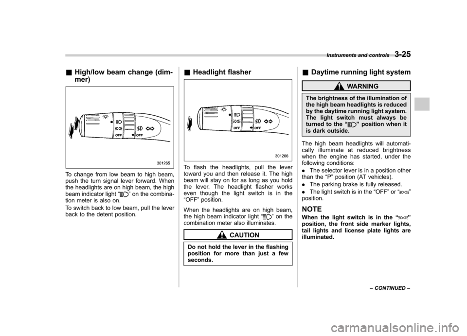
&High/low beam change (dim- mer)
To change from low beam to high beam,
push the turn signal lever forward. When
the headlights are on high beam, the high
beam indicator light “
”on the combina-
tion meter is also on.
To switch back to low beam, pull the lever
back to the detent position. &
Headlight flasher
To flash the headlights, pull the lever
toward you and then release it. The high
beam will stay on for as long as you hold
the lever. The headlight flasher works
even though the light switch is in the“OFF ”position.
When the headlights are on high beam,
the high beam indicator light “
”on the
combination meter also illuminates.
CAUTION
Do not hold the lever in the flashing
position for more than just a fewseconds. &
Daytime running light system
WARNING
The brightness of the illumination of
the high beam headlights is reduced
by the daytime running light system.
The light switch must always be
turned to the “
”position when it
is dark outside.
The high beam headlights will automati-
cally illuminate at reduced brightness
when the engine has started, under the
following conditions: . The selector lever is in a position other
than the “P ”position (AT vehicles).
. The parking brake is fully released.
. The light switch is in the “OFF ”or “
”
position.
NOTE
When the light switch is in the “
”
position, the front side marker lights,
tail lights and license plate lights areilluminated. Instruments and controls
3-25
– CONTINUED –
Page 162 of 384

Air filtration system
Replace the filter element according to the
replacement schedule as follows. This
schedule should be followed to maintain
the filter’s dust collection ability. Under
extremely dusty conditions, the filter
should be replaced more frequently. It is
recommended that you have your filter
checked or replaced by your SUBARU
dealer. For replacement, use only a
genuine SUBARU air filter kit.
Replacement schedule: Every 12 months or 7,500 miles (12,000
km) whichever comes first
CAUTION
Contact your SUBARU dealer if the
following occurs, even if it is not yet
time to change the filter: – Reduction of the air flow through
the vents.
– Windshield gets easily fogged ormisted.
NOTE
The filter can influence the air condi-
tioning, heating and defroster perfor- mance if not properly maintained.
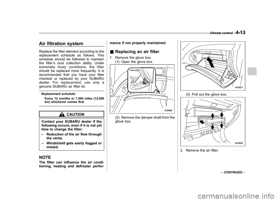
& Replacing an air filter
1. Remove the glove box. (1) Open the glove box.(2) Remove the damper shaft from the
glove box.
(3) Pull out the glove box.
2. Remove the air filter. Climate control
4-13
– CONTINUED –