2009 SKODA ROOMSTER Turn light
[x] Cancel search: Turn lightPage 147 of 263

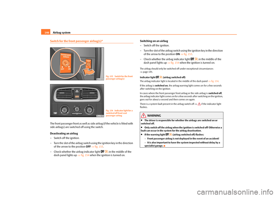
Airbag system 146Switch for the front passenger airbag(s)*The front passenger front as well as side airbag (if the vehicle is fitted with
side airbags) are switched off using the switch.
Deactivating an airbag
– Switch off the ignition.
– Turn the slot of the airbag switch using the ignition key in the direction
of the arrow to the position OFF ⇒fig. 153.
– Check whether the airbag indicator light
in the middle of the
dash panel lights up ⇒fig. 154 when the ignition is turned on.Switching on an airbag
– Switch off the ignition.
– Turn the slot of the airbag switch using the ignition key in the direction
of the arrow to the position ON ⇒fig. 153.
– Check whether the airbag indicator light
in the middle of the
dash panel lights up ⇒fig. 154 when the ignition is turned on.
The airbag should only be switched off under exceptional circumstances
⇒page 145.
Indicator light
(airbag switched off)
The airbag indicator light is located in the middle of the dash panel ⇒fig. 154.
If the airbag is switched on, the airbag warning light comes on for a few seconds
after switching on the ignition.
In cases where the front passenger front airbag or the side airbag is switched off,
the airbag indicator light comes on for a few seconds after switching on the ignition,
goes out for about a second and then comes on again.
There is a system fault present in the airbag switch off ⇒ if the indicator light
flashes.
WARNING
•
The driver is responsible for whether the airbags are switched on or
switched off.
•
Only switch off the airbag when the ignition is switched off! Otherwise a
fault can occur in the system for the airbag deactivation.
•
If the warning light
(airbag switched off) flashes:
−Front passenger airbag is not deployed in the event of an accident!
−It is also important to have the system inspected without delay by a
specialist garage.
Fig. 153 Switch for the front
passenger airbag(s)Fig. 154 Indicator light for a
switched off front seat
passenger airbag
s29g.4.book Page 146 Wednesday, June 17, 2009 9:54 AM
Page 161 of 263

Intelligent Technology 160brake pedal firmly and hold it in this position in order to achieve the shortest
possible braking distance.
The Brake Assist is able to help you achieve a shorter braking distance in emergency
situations by rapidly producing the pressure required in the brake system. It fully
exploits the attributes of the ABS. After you release the brake pedal, the function of
the Brake Assist is automatically switched off and the brakes operate in the normal
way.
The Brake Assist is part of the ESP system. If a fault occurs in the ESP, the Brake Assist
function is also not available. Further information on the ESP ⇒page 155.
WARNING
•
The Brake Assist is also not able to overcome the physical limits of your
vehicle in terms of the braking distance required.
•
Adapt your speed to the conditions of the road surface and to the traffic
situation.
•
The increased safety offered by the Brake Assist must not tempt you to
take a greater safety risk than otherwise.
Electrohydraulic power steeringThe power steering enables you to steer the vehicle with less physical force.
The steering characteristics can be changed by a specialist garage.
You will place great stresses on the power steering system if the steering is turned
to full lock when the vehicle is stationary. Turning the steering to full lock in such a
situation will be accompanied by noises.
It is still possible to fully steer the vehicle if the power steering fails or if the engine
is not running (vehicle being towed in). The only difference is that greater physical
effort is required.
It is possible that the hydraulic pump of the power steering will not run due to the
low vehicle network voltage if the battery has gone flat and the engine must started
with the help off jump leads. This condition will be indicated by lighting up of the
warning light.The power steering operates again if the battery is charged to a specific range when
engine is running. It also operates again, if the engine can be started with its own
battery.
If there is a fault in the power steering, the warning light lights up in the instrument
cluster
⇒page 29.
Caution
Do not leave the steering at full lock for more than 15 seconds when the engine is
running - risk of damaging the power steering!
Note
Have the steering inspected as soon as possible by a specialist garage if there is a
leak or fault in the system.Tyre inflation pressure-control system*The tyre inflation pressure-control system compares with the aid of the ABS sensors
the speed and also the rolling circumference of the individual wheels. If the tyre
inflation pressure is significantly changed and thus the rolling circumference of a
wheel, the warning light
lights up in the instrument cluster ⇒page 35. The tyre
inflation pressure-control system functions late or too sensitively if:
Fig. 167 Button for setting
the tyre inflation pressure
control value
s29g.4.book Page 160 Wednesday, June 17, 2009 9:54 AM
Page 191 of 263

Inspecting and replenishing 190If the coolant level in the reservoir is too low, this is indicated by the warning light
in the instrument cluster
⇒page 32. We nevertheless recommend inspecting
the coolant level directly at the reservoir from time to time.
Loss of coolant
A loss of coolant is first and foremost an indication of a leak in the system. You
should not merely top up the coolant in the reservoir. It is also important to have
the cooling system inspected without delay by a specialist garage.
Losses can only occur through the pressure relief in the cap of the coolant expan-
sion bottle which is completely free of leaks if the coolant boils as a result of over-
heating and is forced out of the cooling system.
WARNING
Read and observe the warning notes ⇒page 185, “Working in the engine
compartment” before working in the engine compartment.
Caution
One should contact a specialist garage as soon as possible if the source of over-
heating itself cannot be determined and removed, since there may be grave
damage to the engine.Replenishing the coolant– Switch the engine off.
– Allow the engine to cool down.
– Place a cloth over the cap of the coolant expansion reservoir
⇒page 189, fig. 179 and unscrew the cap carefully by turning it to the
left ⇒.
– Top up the coolant.
– Screw the cap tight until it is heard to lock.
The coolant which you use for replenishing the system, must comply with one
specific specification ⇒page 189, “Coolant”. Do not use an alternative additive if
the coolant additive G12 PLUS is not available in exceptional cases. Just top up the
system with water and as soon as possible arrange adjustment to correct the mixing
ratio of water and coolant additive again by a specialist garage.
Only use fresh coolant for topping up the system.
Do not fill up over the “MAX” marking! Excess coolant which is heated up is forced
out of the cooling system through the pressure relief valve in the cap of the coolant
compensation bottle.
Wait until the engine has cooled down for a system which has suffered a major loss
of coolant before pouring in coolant. This is necessary to avoid engine damage.
WARNING
•
The cooling system is pressurized! Do not open the cap of the coolant
expansion bottle if the engine is still hot - risk of scalding!
•
The coolant additive and thus all of the coolant is harmful to your health.
Avoid contact with the coolant. Coolant vapours are also harmful to the
health. It is important, therefore, to always safely store any coolant additive
in its original container out of the reach of children - risk of poisoning!
•
If any splashes of coolant get into your eyes, rinse out your eyes immedi-
ately with clear water and contact a doctor as soon as possible.
•
You should also consult a doctor without delay if you have inadvertently
swallowed coolant.Caution
Do not continue your journey if for some reason it is not possible under the
conditions prevailing to top up with coolant. Switch the engine off and obtain
professional assistance from a specialist garage, otherwise it could lead to severe
engine damage.
s29g.4.book Page 190 Wednesday, June 17, 2009 9:54 AM
Page 202 of 263

Wheels and Tyres201
Using the system
Safety
Driving Tips
General Maintenance
Breakdown assistance
Praktik
Technical Data The date of manufacture is also stated on the tyre wall (possibly only on the inside
of wheel).
DOT ... 22 09...
means, for example, that the tyre was manufactured in the 22nd week of the year
2009.
Any spare wheel which differs from the tyres fitted to the vehicle (e.g. winter tyres
or low-profile tyres) should only be used for a short time in the event of a puncture
and when adopting an appropriately cautious style of driving. It should be replaced
as quickly as possible by a normal wheel.
WARNING
•
Only use those tyres or wheel rims which have been approved for your
model of Škoda Auto vehicle. Failure to observe this instruction will
adversely affect the road safety of your vehicle - risk of accident! Approval
and licencing of your vehicle on public roads may also become void as a
result.
•
You must on no account drive at a higher speed than is permissible for
your tyres - risk of an accident resulting from tyre damage and loss of control
over your vehicle.
•
Tyres which are 6 years old or more should only be fitted in exceptional
cases and when adopting an appropriately cautious style of driving.
•
Never fit tyres which have already been used without having adequate
knowledge of their previous history. Tyres age even if they have not been
used at all or only very little. A spare tyre must only be used in exceptional
cases and only then when adopting an appropriately cautious style of
driving.
•
Do not, where possible, replace individual tyres but at least replace them
on both wheels of a given axle at the same time. Always fit the tyres with the
deeper tread depth to the front wheels.For the sake of the environment
Old tyres must be disposed of in conformity with the appropriate regulations.
Note
It is not normally possible to fit wheels from other models of cars for technical
reasons. This may also apply in certain circumstances to the wheels of the same
type of vehicle.Wheel boltsWheels and wheel bolts are matched to each other in terms of design. Each time
you fit other wheels - e.g. light alloy wheels or wheels with winter tyres - you must
therefore also use the matching wheel bolts of the correct length and shape of
spherical cap. This is essential to ensure that the wheels are tightly fitted and that
the brake system operates properly.
If you retrofit wheel trims (or have this done), please also ensure that an adequate
flow of air remains assured for cooling the brake system.
The specialist garages are informed about the technical possibilities which exist
regarding converting or retrofitting wheels, tyres and wheel trims.
WARNING
•
In case of incorrect treatment of the wheel bolts, the wheel can loosen
when the car is moving - risk of accident!
•
The wheel bolts must be clean and must turn easily. However, they must
never be treated with grease or oil.
•
If the wheel bolts are tightened to a too low tightening torque, the rim
can lossen when the car is moving - risk of accident! A tightening torque
which is too high can damage the bolts and threads and this can result in
permanent deformation of the contact surfaces on the rims.Caution
The prescribed tightening torque of the wheel bolts for steel and light alloy wheels
is 120 Nm.
s29g.4.book Page 201 Wednesday, June 17, 2009 9:54 AM
Page 211 of 263

Breakdown assistance 210
– Tighten the wheel bolts firmly, alternately and diagonally using the
wheel wrench ⇒page 211.
– Mount the full wheel trim/wheel trim cap or the caps.
Note•
All bolts must be clean and must turn easily.
•
You must never grease or oil the wheel bolts!
•
When fitting on unidirectional tyres, ensure that the tyres rotate in the correct
direction ⇒page 198.
Subsequent stepsAfter changing the wheel, you must perform the following steps.
– Stow and attach the replaced wheel in the spare wheel well.
– Stow the vehicle tool kit in the space provided.
–Check the tyre pressure on the spare wheel just mounted as soon as
possible.
– Have the tightening torque of the wheel bolts checked with a torque
wrench as soon as possible. The tightening torque for steel and light
alloy wheels must be 120 Nm.
– Have the defective tyre repaired as soon as possible.
WARNING
It is necessary to observe the guidelines given on ⇒page 200, “New tyres
and wheels” if the vehicle is subsequently fitted with tyres which are
different to those it was fitted with at the works.
Note
•
If you find, when changing the wheel, that the wheel bolts are corroded and
difficult to turn, the bolts must be replaced before checking the tightening torque.
•
Drive cautiously and only at a moderate speed to a workshop where the tight-
ening torque can be checked.
Full wheel trim*Pulling off
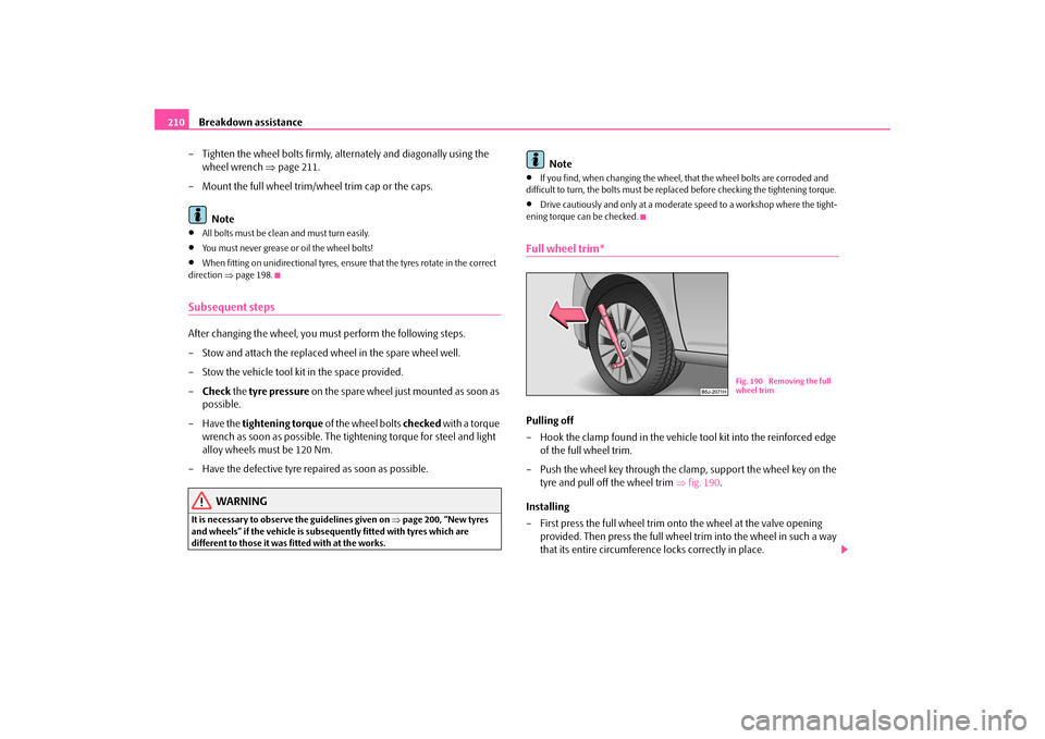
– Hook the clamp found in the vehicle tool kit into the reinforced edge
of the full wheel trim.
– Push the wheel key through the clamp, support the wheel key on the
tyre and pull off the wheel trim ⇒fig. 190.
Installing
– First press the full wheel trim onto the wheel at the valve opening
provided. Then press the full wheel trim into the wheel in such a way
that its entire circumference locks correctly in place.
Fig. 190 Removing the full
wheel trim
s29g.4.book Page 210 Wednesday, June 17, 2009 9:54 AM
Page 216 of 263

Breakdown assistance215
Using the system
Safety
Driving Tips
General Maintenance
Breakdown assistance
Praktik
Technical Data
Tow-starting and towing vehicleGeneralPlease pay attention to the following instructions if you are going to use a
tow rope:
Driver of the towing vehicle
– Do not drive off until the tow rope is taught.
– Release the clutch particularly gently when starting off.
Driver of the towed vehicle
– Switch the ignition on so that the steering wheel is not blocked and
you can also operate the turn signal lights, the headlight flasher, the
windscreen wipers and windscreen washer system.
– Take the vehicle out of gear or move the selector lever into position N
if your vehicle is fitted with an automatic gearbox.
– Note that the brake servo unit and power steering only operate if the
engine is running. You will require significantly greater physical force
to depress the brake pedal and to steer the vehicle if the engine is not
running.
– Ensure that the tow rope is always kept taught.Tow rope or tow bar
A tow bar is safest way of towing a vehicle and also minimizes any shocks. You can
use a tow rope only if a suitable tow bar is not available.
The tow rope must be elastic to protect the vehicle. Thus one should only use
plastic fibre rope or a rope made out of a similarly elastic material.
Attach the tow rope or the tow bar only to the towing eyes provided for this
purpose ⇒page 215, “Front towing eye” and ⇒page 216, “Rear towing eye”.Driving style
Towing another vehicle requires a certain amount of practice. Both drivers should
be familiar with the particular points about towing a vehicle. Unskilled drivers
should not attempt to tow in another vehicle or to be towed in.
One should be constantly vigilant not to allow impermissibly high towing forces or
jerky loadings. There is always a risk of excessive stresses and damage resulting at
the points to which you attach the tow rope or tow bar when you attempt to tow a
vehicle which is not standing on a paved road.
Caution
If the gearbox of your vehicle no longer contains any oil because of a defect, your
vehicle must only be towed in with the driven wheels raised clear of the ground, or
on a special vehicle transporter or trailer.
Note
•
Please comply with any legal requirements particularly regarding the switched
on signal systems, when towing in or tow-starting another vehicle.
•
The tow rope must not be twisted as it may in certain circumstances result in the
front towing eye being unscrewed out of your vehicle.
Front towing eye
The towing eye is stored in the box for the vehicle tool kit.
Fig. 196 Front bumper:
Protective grille
s29g.4.book Page 215 Wednesday, June 17, 2009 9:54 AM
Page 225 of 263

Fuses and light bulbs 224
WARNING
•
Bulbs H7 and H4 are pressurised and may burst when changing the bulb
- risk of injury!
•
It is recommended to wear gloves and eye protection when changing a
light bulb.Note
This Owner's Manual only describes the replacement of bulbs where it is assumed
that no major complications will arise. Other light bulbs should be replaced by your
specialist garage.Front headlight
Front headlight
Reflector
Module
Low beam and main beam
H4
H7
Parking lights
W5W
Turn signals
PY21W
Fog lights
HB4
Fog lights with the function
“Corner”
H8
Rear light unit
Bulb
Reversing light
P21W
Turn signals
PY21W
Brake lights
P21W
Fog lights
P21W
Parking lights
2x W5W
Others
Bulb
Side turn signal lights
WY5W
Licence plate light
C5W / T4W (5W)
3. Brake light
LED
Interior lighting front / rear
C10W
Reading lights
W5W
Luggage compartment light
W5W
Storage compartment light - front passenger
side
W5W
Fig. 207 Front headlight:
Fitting position of the bulbs
s29g.4.book Page 224 Wednesday, June 17, 2009 9:54 AM
Page 226 of 263

Fuses and light bulbs225
Using the system
Safety
Driving Tips
General Maintenance
Breakdown assistance
Praktik
Technical Data
– Open the bonnet.
– For a vehicle with petrol engine remove the activated charcoal filter
system before replacing the bulb in the right front headlight
⇒fig. 208.Positions of the light bulbs in the front headlight ⇒page 224, fig. 207.
- low beam and main beam
- parking lights
- Turn signal light (at the front)
Switching on the low beam and main beam– Open the bonnet.
– Remove the protective cap ⇒page 224, fig. 207.
– For headlights with module (halogen lamp H7) ⇒fig. 209 turn the
connector with the halogen lamp to the left up to the stop and
remove.
– For headlights with reflector (halogen lamp H4) pull off the connector
from the lamp, release the sprung wire clamp and pull out the halogen
lamp towards the rear.
– Replace the halogen lamp H7, insert the connector with the new
halogen lamp and turn to the right up to the stop.
– Replace the halogen lamp H4, insert into the opening in the reflector
(with the fixing lugs in the recesses), secure with the sprung wire
clamp, position the protective cap and mount the connector.
– We recommend that you have the headlight setting checked by a
Skoda Service Partner after replacing the light bulb.
Fig. 208 Removing the acti-
vated charcoal filter system
AAABAC
Fig. 209 Removing the light
bulb for the low beam and
main beam light
AA
s29g.4.book Page 225 Wednesday, June 17, 2009 9:54 AM