Page 57 of 63

62C-57
MR-413-X44-62C000$910_eng.mif
V1
MANUAL AIR CONDITIONING
Fault finding - Fault finding charts62C
ALP 9
CONTINUED
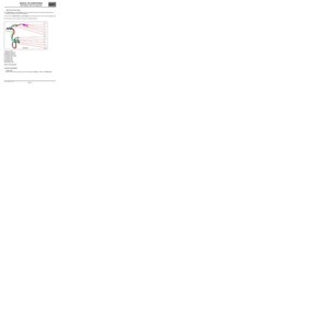
With the engine warm and passenger compartment
ventilation operating, vary the position of the mixing
flap from the maximum cold position to the
maximum hot position and check subjectively that
there is a difference in temperature.
Is a difference in temperature noted?
YES
Using the diagnostic tool statuses and parameters
screen (UCH heating sub-function), check that the
temperature signals are consistent (no sensor
deviations resulting in incorrect measurement).
–Use statuses PR002 Exterior temperature and
PR024 Coolant temperature.
Are the temperature signals consistent?
YES
Check the refrigerant fluid (see Technical Note
6001A, Air conditioning, 62A, Air conditioning,
Air conditioning: Check).
NOCheck the condition and routing of the
mixing flap control cable. Eliminate any
constraints on the cable: kinks, restricted
by plastic clips, etc. Replace it if
necessary. Unclip the cable from the side
of the unit and check the stiffness of
movement of each component: control
button and flap control on the air
distribution unit. Check that there is no
mechanical fault on the mixing flap (flap
jammed inside the unit, etc.).
Carry out any necessary repairs.
NOCarry out a conformity check:
–For the coolant temperature sensor, see
13B, Diesel injection, Fault summary
table or 17B Petrol injection, Fault
summary table.
–For the exterior temperature sensor,
see 87B, Passenger compartment
connection unit, Fault summary
table.
Replace any faulty components.
AFTER REPAIRCarry out a complete check with the diagnostic tool.
Page 58 of 63

62C-58
MR-413-X44-62C000$910_eng.mif
V1
MANUAL AIR CONDITIONING
Fault finding - Fault finding charts62C
ALP 10 Inefficient rear screen de-icing/demisting
NOTESCarry out this conformity check after a full check using the diagnostic tool (fault
reading, especially UCH and injection faults and configuration checks).
Check that the fuses are sound.
Use a multimeter and a 21 W test light.
Use the Wiring Diagram Technical Note, New Twingo.
Special notes:
Check that the inside of the windows are not greasy as this reduces the efficiency of
the de-icing.
Note:
The de-icing control is only authorised when the engine is running to save
power. The rear screen de-icer is controlled by pressing the rear screen de-icer
button (with time delay and rear-view mirror de-icer if fitted).
Ensure that there are no water leaks in the passenger compartment which would significantly increase the
moisture and reduce the effectiveness of the demisting function (see ALP 12 if the fault is noted).
Is the fault still present?
YES NO
Check that the UCH receives the signal about the
status and operation of the engine. In the Cold Loop
screen, status ET142 Engine operating phase
should display RUNNING.
Is status ET142 RUNNING?
YES
End of fault finding procedure.
NOCarry out fault finding on the UCH
(interpretation of status ET142) and on the
multiplex network.
AFTER REPAIRCarry out a complete check with the diagnostic tool.
Page 59 of 63

62C-59
MR-413-X44-62C000$910_eng.mif
V1
MANUAL AIR CONDITIONING
Fault finding - Fault finding charts62C
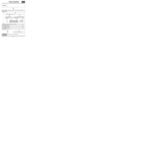
ALP 10
CONTINUED
Press the de-icing button on the control panel and
check status:
–ET028 Heated rear screen button
Does status ET028 display PRESSED?
YES
Connect a test light between connections 15LP and
MYH of component 200 and, using the diagnostic
tool, run command AC060 Rear screen de-icer
(UCH command mode menu).
Does the test light illuminate?
YES
Connect a test light between connection 15LP and
the chassis earth and use the diagnostic tool to
run command AC060 Rear screen de-icer (UCH
command mode menu).
Does the test light illuminate?
NO
Check the continuity of connection 15LP between
components 200 and 645.
Is the continuity correct?
YES
See 87B, UCH, Interpretation of commands, for command AC060 Rear screen de-icer.
NOContinuity fault on connection 15M.
Using an ohmmeter, carry out a continuity
test on connection 15M between
components 319 and 645. If there is a
procedure (see Technical Note 6015A,
Repairing electrical wiring, Wiring:
Precautions for repair), repair the wiring,
otherwise replace the wiring.
NOCheck the resistance of the rear screen
de-icer lines. The line resistance must not
be zero or infinite. If the resistance is not
correct, replace the rear screen (see MR
412, Bodywork, 54A, W indows, Rear
screen window: Removal - Refitting).
YESContinuity fault on connection MYH of
component 200. If there is a repair method
(see Technical Note 6015A, Repairing
electrical wiring, Wiring: Precautions
for repair), repair the wiring, otherwise
replace the wiring.
NOContinuity fault on connection 15LP
between components 200 and 645. If
there is a repair method (see Technical
Note 6015A, Repairing electrical wiring,
Wiring: Precautions for repair), repair
the wiring, if not replace the wiring.
AFTER REPAIRCarry out a complete check with the diagnostic tool.
Page 60 of 63

62C-60
MR-413-X44-62C000$910_eng.mif
V1
MANUAL AIR CONDITIONING
Fault finding - Fault finding charts62C
ALP 11 Unpleasant odours in the passenger compartment
NOTESNone.
Check that the cabin filter is not blocked or
damaged.
Is the fault still present?
YES
Check that the condensate drain pipe (water from
the evaporator) is not blocked.
Is the fault still present?
YES
Check that there are no leaks on the heating unit in
relation to the engine compartment:
- Foam seal on the heater matrix coolant pipes fitted
and in good condition.
- Rubber seal on the radiator tank fitted and in good
condition (seal under the bonnet separating the
engine compartment from the windscreen aperture).
- Drain valve on the radiator tank fitted and in good
condition.
Repair if necessary.
Is the fault still present?
YES
Remove the cabin filter to apply air conditioning
system cleaner using an extension pipe on the
evaporator.
Spray the entire contents of the aerosol.
Leave the product to work for 15 minutes.
NOEnd of fault finding procedure.
NOEnd of fault finding procedure.
NOEnd of fault finding procedure.
AFTER REPAIRCarry out a complete check with the diagnostic tool.
Page 61 of 63
62C-61
MR-413-X44-62C000$910_eng.mif
V1
MANUAL AIR CONDITIONING
Fault finding - Fault finding charts62C
ALP 12 Water is present in the passenger compartment
NOTESNone.
Pressurise the cooling circuit.
Is there any coolant leaking into the vehicle?
NO
Check that the condensate drain pipe (water from
the evaporator) is not blocked.
Repair if necessary.
Is the fault still present?
YES
Make sure that the scuttle panel (under the windscreen aperture) is not filled with water.
If it is, check that the drain valve is fitted to the scuttle panel and is in good condition.
Replace the valve if necessary.
Has the customer just washed the vehicle?
YES
Explain to the customer that when washing the car
using a hose pipe, the water jet must not be left for
too long on the air inlet in the scuttle panel (on the
bonnet).
YES Repair.
NOEnd of fault finding procedure.
NO End of fault finding procedure.
AFTER REPAIRCarry out a complete check with the diagnostic tool.
Page 62 of 63

62C-62
MR-413-X44-62C000$910_eng.mif
V1
MANUAL AIR CONDITIONING
Fault finding - Fault finding charts62C
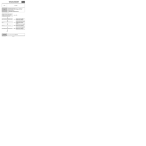
ALP 13 No lighting on the control panel in night mode
NOTESCheck fuse F42-10A of component 1016.
Using a test light, check for + 12 V between connection LPD and connection NAM of component 319.
Does the test bulb illuminate?
YES NO
Check the condition of the air conditioning control
panel bulbs.Carry out a continuity test on connection LPD
between component 319 and F42-10A of component
1016.
Are the bulbs sound? Is the test correct?
YES NO YES NO
Replace the air
conditioning control
panel.Replace the air
conditioning control
panel bulb(s).Using the test light,
check for + 12 V
between connection
LPD of component 319
and the chassis earth.Fault on connection LPD
between F42-10A of
components 1016 and
319. Repair the wiring. If
there is a repair
procedure (see
Technical Note 6015A,
Repairing electrical
wiring, Wiring:
Precautions for repair),
repair the wiring,
otherwise replace it.
Is the test correct?
NO YES
Replace the air conditioning control panelFault on connection NAM. Repair the wiring. If there is
a repair procedure (see Technical Note 6015A,
Repairing electrical wiring, W iring: Precautions
for repair), repair the wiring, otherwise replace it.
AFTER REPAIRCarry out a complete check with the diagnostic tool.
Page 63 of 63

62C-63
MR-413-X44-62C000$910_eng.mif
V1
MANUAL AIR CONDITIONING
Fault finding - Fault finding charts62C
ALP 14 Noisy compressor
NOTESConsult this customer complaint after a full check with the diagnostic tool (fault
reading and configuration checks).
WARNING
Check that the computers active in the AIR CONDITIONING function (Injection and
UCH) are correctly configured.
Note:
Before starting any work, check that the noise is indeed coming from the compressor.
Check that the compressor belt is in good condition and check its tension (for engines without automatic
tensioning) (see MR 411, Mechanical, 11A, Top and front of engine, Accessories belt: Removal - Refitting).
Check that the compressor is correctly fixed (see MR 411 Heating and air conditioning system, 62A, Air
conditioning, Compressor: Removal - Refitting).
Check the refrigerant fluid and look for any leaks. Significant loss of fluid causes the compressor to make noises.
(see Technical Note 6001A, Air conditioning, 62A, Air conditioning, Air conditioning: Check).
If the fault is still present, replace the air conditioning compressor (see MR 411, Mechanical, 62A, Air
conditioning, Compressor: Removal - Refitting).
AFTER REPAIRCarry out a complete check with the diagnostic tool.