Page 9 of 63
62C-9
MR-413-X44-62C000$273_eng.mif
V1
62C
MANUAL AIR CONDITIONING
Fault finding - Role of components
COLD LOOP COMPONENTS
System assembly
1Air conditioning unit
2Heater matrix
3Expansion valve and evaporator
4Coolant circuit
5Cold loop
6Condenser and radiator
7Compressor
Figure 1: System assembly
–Compressor:
The compressor is not activated when the exterior temperature is less than 0˚; it is used to compress the refrigerant
fluid into gas. The pressure can reach up to 28 bar.
MR-413-X44-62C000$273_eng.mif
Page 10 of 63

62C-10
MR-413-X44-62C000$273_eng.mif
V1
MANUAL AIR CONDITIONING
Fault finding - Role of components62C
–Condenser:
The condenser is composed of flat horizontal aluminium tubes. The pipes are divided by the vanes in order to
increase the air heat exchange and therefore cool the refrigerant fluid to produce condensation.
1Condenser
2Dehydration canister
–Dehydrator reservoir:
The dehydrator reservoir is used to:
●Check the condition of the refrigerant.
●Absorb the variations in volume (expansion bottle principle).
●Filter impurities.
●Absorb moisture (water in the circuit).
–Air conditioning unit:
This unit acts as an air mixing box. It is equipped with a system of flaps which allow the air to be directed in
accordance with the requirements of the occupants whilst simultaneously allowing the temperature of the air
entering the passenger compartment to be modified by mixing hot and cold air.
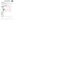
–Thermostatic expansion valve: (see figure below)
This thermostatic-type expansion valve is used to check refrigerant expansion. It is located at the evaporator inlet.
–Evaporator: (see figure below)
●The evaporator is a heat exchanger which enables the air entering the passenger compartment to be cooled.
Note: Condensation of the air may occur thereby causing normal drops of water to form under the body.
1
1Expansion valve
2Evaporator
Page 11 of 63
62C-11
MR-413-X44-62C000$273_eng.mif
V1
MANUAL AIR CONDITIONING
Fault finding - Role of components62C
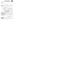
–High and low pressure pipes:
●The High Pressure and Low Pressure pipes are composed of rigid aluminium pipes and flexible pipes that
enable engine-related movements to be absorbed.
●Two filler valves (High Pressure and Low Pressure) can be accessed in order to fill (or drain) the refrigerant loop.
●The connections must be checked in the event of a refrigerant fluid leak.
1Buffering capacity
2Expansion valve outlet
3Expansion valve inlet
4High pressure filler valve
5Low pressure filler valve
6Condenser inlet
7Condenser outlet
8Pressure sensor
9Compressor inlet
10 Compressor outlet
Figure 6: Cold loop pipes
●HEATING COMPONENTS
–Heater matrix:
The external air entering the heating and air conditioning device (HVAC) is heated by the heater matrix.
Page 12 of 63
:
The passenger comp")
62C-12
MR-413-X44-62C000$273_eng.mif
V1
MANUAL AIR CONDITIONING
Fault finding - Role of components62C
–Passenger compartment heating resistors (depending on the equipment level):
The passenger compartment heating resistors (RCH) are electrical heating devices in the air conditioning unit. This
system is an additional heating system which operates when the engine is cold (when starting).
ACTUATORS
–Air distribution flap:
This flap enables the air flowing into the passenger compartment to be directed.
–Air mixing flap:
This flap mixes the air in order to meet the temperature requirements of the occupants.
–Recirculation flap:
This flap prevents the entry of exterior air. In this case, the passenger compartment is isolated from the exterior and
air is blown in the passenger compartment in a closed circuit.
These three flaps are controlled by a cable.
●OTHERS
–Passenger compartment blower unit:
The passenger compartment blower unit is controlled by the Resistive Blower Dimmer Module (MVPR).
Page 13 of 63

1Thermal fuse
2Fan assembly connector
3Connector to Control")
62C-13
MR-413-X44-62C000$273_eng.mif
V1
MANUAL AIR CONDITIONING
Fault finding - Role of components62C
Resistive Blower Dimmer Module (MVPR)
1Thermal fuse
2Fan assembly connector
3Connector to Control panel
The passenger compartment blower unit is used to vary the rate at which air is blown into the passenger
compartment, depending on the requirements of the customer.
–Cooling fan assembly:
The cooling fan assembly motor is normally used in order to promote heat exchange in the condenser and therefore
improve the performance of the air conditioning system. Activation of the air conditioning fan unit depends, among
other things, on the vehicle speed and high pressure in the loop.
–Air pipes:
The air flows into an open air inlet scoop towards the exterior. Therefore there must be enough air flow for it to be
channelled into the passenger compartment. This flow can be created by the vehicle speed (in non-recirculation
mode) or by activating the blower. The air flowing into the passenger compartment is protected by a grille and a rain
shield in order to prevent foreign bodies and water from entering. The air is then distributed inside the passenger
compartment.
Passenger compartment air pipes
1Air inlet
2De-icing
3Right-hand air vent
4Left-hand air vent
5Centre air vents
6Left-hand footwell vent
7Right-hand footwell vent
Page 14 of 63
62C-14
MR-413-X44-62C000$364_eng.mif
V1
62C
MANUAL AIR CONDITIONING
Fault finding - Operating diagram
Summary diagram of all the components of the air conditioning system
1Evaporator
2Temperature sensor
3Compressor
4Condenser
5Fan assembly
6Pressure switch
7Dehydration canister
8Expansion valve
MR-413-X44-62C000$364_eng.mif
Page 15 of 63
62C-15
MR-413-X44-62C000$455_eng.mif
V1
62C
MANUAL AIR CONDITIONING
Fault finding - Function
Layout of the air conditioning function:
The “air conditioning” function is divided between two computers. These two computers are connected by the CAN
multiplex network; the connection between the air conditioning control panel and the UCH is provided by a wire
connection.
The air conditioning control panel interprets the driver's demands.
The UCH sends the request for compressor activation to the injection system.
The injection computer controls the passenger compartment heating resistors (depending on the equipment).
It authorises or denies compressor activation depending on the vehicle operation and refrigerant pressure.
Air conditioning control panel: front panel
Passenger compartment ventilation and heating control rear panel
MR-413-X44-62C000$455_eng.mif
Page 16 of 63

62C-16
MR-413-X44-62C000$455_eng.mif
V1
MANUAL AIR CONDITIONING
Fault finding - Function62C
General operation
The air conditioning system is composed of four sub-functions: heating, cold loop, passenger compartment
ventilation and user selection. Fault finding on the air conditioning is performed in two different ways using the
diagnostic tool.
The first procedure consists of performing fault finding on each computer which allows dialogue to be established
with just one computer (select the UCH computer).
The second procedure consists of performing fault finding on each function which allows communication with both
computers of the air conditioning function.
Description of the sub-functions:
Heater sub-system: this sub-system includes everything relating to the production of warm air in the vehicle and
management of the heated rear screen.
The UCH computer controls the rear screen de-icing.
The injection computer manages passenger compartment heating resistor actuation
Cold loop sub-system: this sub-system includes everything involved in the production of cold air in the vehicle.
The computers concerned include:
The injection computer, which authorises compressor activation and controls the compressor and motor-driven fan
assemblies.
The UCH, which authorises or denies the request for compressor activation from the air conditioning control panel to
the injection computer in accordance with the condition of the passenger compartment blower and the exterior
temperature (depending on the equipment).
User selection sub-function: This sub-function includes everything used to transmit the user's requests (pressing
buttons). The computer involved is the UCH computer.