Page 257 of 348

17B-257V7 MR-413-X44-17B000$153.mif
PETROL INJECTION
Fault finding – Interpretation of statuses17B
SIM 32 Injection
Program no.: D3
Vdiag No.: 44, 4C, 50
and 54
ET703
CONTINUED 2
INCREASE
Status ET703 becomes INCREASE when the cruise control/speed limiter + button is
pressed. This button is on the steering wheel, on the left-hand side.
To carry out the checks and measurements in complete safety, observe the driver's
frontal airbag removal recommendations (see MR 392 (Clio III), MR 385 (Modus),
MR 411 (New Twingo), or MR 442 (E33), Mechanical, 88C, Airbag and
pretensioners, Driver's frontal airbag: Removal - Refitting).
If status ET703 does not display INCREASE, check the condition of the cruise
control/speed limiter +/- button, and the condition of its connector.
If the connector is faulty and there is a repair method (see Technical Note 6015A,
Repairing electrical wiring, Wiring: Precautions for repair), repair the connector,
otherwise replace the wiring.
Measure the resistance of the following connections while pressing the + button
(on the button connections):
●86G of component 331.
●86M of component 331.
If the resistance is not X ≈ 300 Ω, check the continuity of the connection when the
button is in the rest position.
If there is continuity, replace the +/- control button.
AFTER REPAIRCarry out a road test, then check with the diagnostic tool.
Page 258 of 348

17B-258V7 MR-413-X44-17B000$153.mif
PETROL INJECTION
Fault finding – Interpretation of statuses17B
SIM 32 Injection
Program no.: D3
Vdiag No.: 44, 4C, 50
and 54
ET703
CONTINUED 3
DECREASE
Status ET703 becomes MINUS when the cruise control/speed limiter "-" button is
pressed. This button is on the steering wheel, on the left-hand side.
To carry out the checks and measurements in complete safety, observe the driver's
frontal airbag removal recommendations (see MR 392 (Clio III), MR 385 (Modus),
MR 411 (New Twingo), or MR 442 (E33), Mechanical, 88C, Airbag and
pretensioners, Driver's frontal airbag: Removal - Refitting).
If status ET703 does not change to DECREASE, check the condition of the cruise
control/speed limiter +/- button and check the condition of its connector.
If the connector is faulty and there is a repair method (see Technical Note 6015A,
Repairing electrical wiring, Wiring: Precautions for repair), repair the connector,
otherwise replace the wiring.
Measure the resistance of the following connection while pressing the "-" button
(on the button connections):
●86G of component 331.
●86M of component 331.
If the resistance is not X ≈ 100 Ω, check the continuity of the connection when the
button is in the rest position.
If there is continuity, replace the +/- control button.
SUSPENDStatus ET703 becomes SUSPEND when the cruise control/speed limiter "0" button
is pressed. This button is located on the steering wheel, to the right.
To carry out the checks and measurements in complete safety, observe the driver's
frontal airbag removal recommendations (see MR 392 (Clio III), MR 385 (Modus),
MR 411 (New Twingo), or MR 442 (E33), Mechanical, 88C, Airbag and
pretensioners, Driver's frontal airbag: Removal - Refitting).
If status ET703 does not become SUSPEND, check the condition of the cruise
control/speed limiter "R/0" button and the condition of its connector.
If the connector is faulty and there is a repair method (see Technical Note 6015A,
Repairing electrical wiring, Wiring: Precautions for repair), repair the connector,
otherwise replace the wiring.
Measure the resistance of the following connection while pressing the "0" button
(on the button connections):
●86G of component 331.
●86M of component 331.
If the resistance is not X ≈ 0 Ω, replace the R/0 control button.
If there is continuity, replace the R/0 control button.
AFTER REPAIRCarry out a road test, then check with the diagnostic tool.
Page 259 of 348

17B-259V7 MR-413-X44-17B000$153.mif
PETROL INJECTION
Fault finding – Interpretation of statuses17B
SIM 32 Injection
Program no.: D3
Vdiag No.: 44, 4C, 50
and 54
ET703
CONTINUED 4
RESUME
Status ET703 becomes RESUME when the cruise control/speed limiter "R" button is
pressed. This button is located on the steering wheel, to the right.
To carry out the checks and measurements in complete safety, observe the driver's
frontal airbag removal recommendations (see MR 392 (Clio III), MR 385 (Modus),
MR 411 (New Twingo), or MR 442 (E33), Mechanical, 88C, Airbag and
pretensioners, Driver's frontal airbag: Removal - Refitting).
If status ET703 does not change to RESUME, check the status of the cruise control/
speed limiter R/0 button and the condition of its connector.
If the connector is faulty and there is a repair method (see Technical Note 6015A,
Repairing electrical wiring, Wiring: Precautions for repair), repair the connector,
otherwise replace the wiring.
Measure the resistance of the following connection while pressing the R button
(on the button connections):
●86G of component 331.
●86M of component 331.
If the resistance is not X ≈ 900 Ω, check the continuity of the connection when the
button is in the rest position.
If there is continuity, replace the R/0 control button.
AFTER REPAIRCarry out a road test, then check with the diagnostic tool.
Page 260 of 348

17B-260V7 MR-413-X44-17B000$153.mif
PETROL INJECTION
Fault finding – Interpretation of statuses17B
SIM 32 Injection
Program no.: D3
Vdiag No.: 44, 4C, 50
and 54
ET704
ET705BRAKE SWITCH NO. 1BRAKE SWITCH NO. 2
STATUS
DEFINITIONACTIVE: This status indicates that the brake pedal is depressed.
INACTIVE: This status indicates that the brake pedal is released.
NOTESSpecial notes:
Only perform these tests if the parameters do not correspond with the system operation
programming.
Note:
Statuses ET704 and ET705 should change status at the same time. If there is
inconsistency, refer to the interpretation of faults DF228 Brake signals and DF623
Closing brake signal.
Use the Wiring Diagrams Technical Note for NEW TWINGO, E33, CLIO III
or MODUS.
Conformity check: Engine stopped and ignition on, or engine running, and engine coolant
temperature > 80˚C
"ACTIVE"Brake pedal depressed.
Brake signal non-conformity may cause the engine to race during gear changes.
"INACTIVE"Brake pedal released.
Brake signal non-conformity may cause the engine to race during gear changes.
SIM32_V44_ET704 / SIM32_V4C_ET704 / SIM32_V50_ET704 / SIM32_V54_ET704
SIM32_V44_ET705 / SIM32_V4C_ET705 / SIM32_V50_ET705 / SIM32_V54_ET705
AFTER REPAIRCarry out a road test, then check with the diagnostic tool.
Page 261 of 348

17B-261V7 MR-413-X44-17B000$153.mif
PETROL INJECTION
Fault finding – Interpretation of statuses17B
SIM 32 Injection
Program no.: D3
Vdiag No.: 44, 4C, 50
and 54
ET704
ET705
CONTINUED
Sensor electrical conformity
ACTIVE
or
INACTIVE
If the brake lights are working:
–Check the continuity and the absence of interference resistance of the
following connections:
●5A between components 160 and 120/645/119 (for NEW TWINGO or E33)
●65A between the components 160 and 120/645/119 (for CLIO III or MODUS).
If the connections are faulty and if there is a repair procedure (see Technical Note
6015A, Electrical wiring repair, Wiring: Precautions for repair), repair the wiring,
otherwise replace the wiring.
If the brake lights are not operational, check:
–the condition and fitting of the brake switch,
–the condition and conformity of the brake lights fuse.
–the conformity of the values in the following tables:
Continuity
between
connectionsInsulation
between
connections
Switch
pressed
(Brake pedal
released)For CLIO III or
MODUS5A and SP13 65G and AP10
For NEW
TWINGO or E335A and AP10 65A and AP10
Switch
released
(Brake pedal
depressed)For CLIO III or
MODUS65G and AP10 5A and SP13
For NEW
TWINGO or E3365A and AP10 5A and AP10
Replace the switch if the values obtained are not correct.
AFTER REPAIRCarry out a road test, then check with the diagnostic tool.
Page 262 of 348
17B-262V7 MR-413-X44-17B000$153.mif
PETROL INJECTION
Fault finding – Interpretation of statuses17B
SIM 32 Injection
Program no.: D3
Vdiag No.: 50 and 54
ET840CUSTOMISED OIL CHANGE INTERVAL
STATUS
DEFINITIONACTIVE: This status indicates that the OCS function is active.
INACTIVE: This status indicates that the OCS function is inactive.
NOTESNone.
Conformity check: Engine stopped and ignition on, or engine running at idle speed, and engine coolant
temperature > 80˚C.
ACTIVE
or
INACTIVE
This status indicates if the vehicle offers the OCS (Oil Control System) function, i.e.
the customised oil change interval.
SIM32_V50_ET840 / SIM32_V54_ET840
AFTER REPAIRCarry out a road test, then check with the diagnostic tool.
Page 263 of 348

17B-263V7 MR-413-X44-17B000$160.mif
17B
SIM 32 Injection
Program no.: D3
Vdiag No.: 44, 4C, 50
and 54
* OCR: Opening cyclic ratio
* EV: Solenoid valve
* mot: motorised
* app.: applying
* AAC: Camshaft
Tool ParameterDiagnostic tool title
PR014Idling speed correction
PR015Engine torque
PR018Estimated air flow
PR030Accelerator pedal position
PR035Atmospheric pressure
PR037Refrigerant pressure
PR041Turbocharger pressure (Vdiag 54 only)
PR055Engine speed
PR059Inlet air temperature
PR064Coolant temperature
PR071Computer feed voltage
PR089Vehicle speed
PR090Idle speed regulation programming value
PR091OCR* Theoretical idle speed regulation
PR094AAC* dephaser OCR* setpoint (Vdiag 4C only)
PR095Anti-pinking correction
PR096Mot.* throttle upper stop programmed value.
PR097Mot.* throttle lower stop programmed value.
PR098Upstream oxygen sensor voltage
PR099Downstream oxygen sensor voltage
PR101Duration of injection
PR102Canister bleed solenoid valve OCR*
PR103Instantaneous fuel consumption
PR104Turbocharging EV* OCR* (Vdiag 54 only)
PR105Mileometer OBD fault warning light lit
PR106Mileometer fault warning light lit
PR111Motorised throttle position corrected value.
PR113Lower throttle stop after app.* offset
PR116Motorised throttle corrected position setpoint
PR118Measured throttle position gang 1
PR119Measured throttle position gang 2
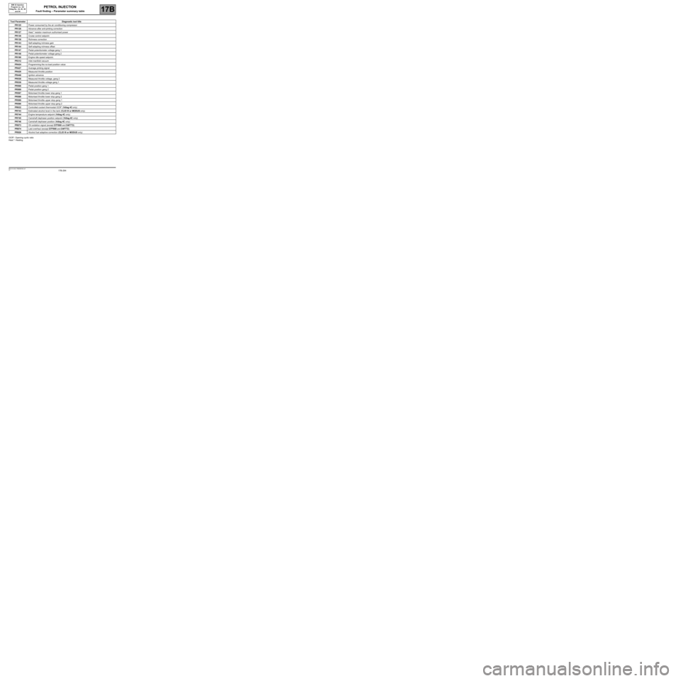
PETROL INJECTION
Fault finding – Parameter summary table
Page 264 of 348

17B-264V7 MR-413-X44-17B000$160.mif
PETROL INJECTION
Fault finding – Parameter summary table17B
SIM 32 Injection
Program no.: D3
Vdiag No.: 44, 4C, 50
and 54
OCR*: Opening cyclic ratio
Heat.*: Heating
Tool ParameterDiagnostic tool title
PR125Power consumed by the air conditioning compressor
PR126Advance after anti-pinking correction
PR127Heat.* resistor maximum authorised power
PR130Cruise control setpoint
PR138Richness correction
PR143Self-adapting richness gain
PR144Self-adapting richness offset
PR147Pedal potentiometer voltage gang 1
PR148Pedal potentiometer voltage gang 2
PR190Engine idle speed setpoint.
PR312Inlet manifold vacuum
PR424Programming the no-load position value
PR427Average pinking signal
PR429Measured throttle position
PR448Ignition advance
PR538Measured throttle voltage, gang 2
PR539Measured throttle voltage gang 1
PR568Pedal position gang 1
PR569Pedal position gang 2
PR587Motorised throttle lower stop gang 1
PR588Motorised throttle lower stop gang 2
PR589Motorised throttle upper stop gang 1
PR590Motorised throttle upper stop gang 2
PR632Controlled coolant thermostat OCR* (Vdiag 4C only)
PR743Estimated alcohol level in the tank (CLIO III or MODUS only)
PR744Engine temperature setpoint (Vdiag 4C only)
PR745Camshaft dephaser position setpoint (Vdiag 4C only)
PR746Camshaft dephaser position (Vdiag 4C only)
PR873Oil oxidation signal (except D7F800 and D4F772)
PR874Last overhaul (except D7F800 and D4F772)
PR926Alcohol fuel adaptive correction (CLIO III or MODUS only)